Wide-Temperature Adhesives: −70 °C to 300 °C Bonding, CTE Matching and Device-Level Validation
SCITEO converges low-temperature toughness, high-Tg backbone and low-shrinkage control into one qualification flow: modulus-plateau flatness, fracture toughness and TC1500/THS1500 retention — a wide-temperature selection guide
Abstract
−70 °C to +300 °C is the band where volume demand is densest across industrial control, automotive electronics, military components and optoelectronics, and where wide-temperature adhesive selection tests engineering judgement hardest. The trap engineers fall into most often is fixing on the two endpoint numbers; what actually decides whether the interface survives is three measurable quantities: the flatness of the storage-modulus spectrum across the whole band, the CTE mismatch against dissimilar substrates, and the interfacial strength retained after thermal aging and thermal cycling. SCITEO Advanced Materials' wide-temperature epoxy platform condenses −70 °C toughness, 300 °C long-term service and 260 °C peak process thermal shock into one formulation: shear strength holds at 18 MPa or above at −70 °C without brittle cracking, and after 1,500 extended thermal cycles and 1,500 hours of 85/85 damp-heat bias the interfacial shear retention stays at 95% and 90% respectively. Deeper cold duty (liquid nitrogen down to the −225 °C class) and hotter duty (300 °C to 1,000 °C ultra-high-temperature grades) are handled by dedicated formulation routes; this article stays inside the −70 °C to +300 °C band, where engineering demand is densest.
The difficulty of that band is that the two ends pull in opposite directions. The cold end needs retained chain-segment freedom, suppressed modulus rise and preserved fracture toughness; the hot end needs bond energy and oxidation stability in the crosslinked network, with expansion and dielectric decay held down. In service a device accumulates long-term mid-temperature aging, intermittent peak thermal shock and thousands of thermal cycles at once, and the mechanisms differ from one another, so the combined damage arrives far earlier than any single temperature point would suggest.
The article follows two threads, failure physics (physics of failure, PoF) and validation methodology, and closes with device-level criteria for a set of advanced applications.
Key Parameter Comparison
The table below is one we attach to the first technical pack a customer receives. The industry-baseline column is drawn from public technical data and typical values for common general-purpose systems, not from deliberately weak samples, and the same pack carries the DMA, TMA and post-cycling retention curves so the numbers and the curves can be checked against each other.
| Parameter | SCITEO | Industry Baseline | Test Standard |
|---|---|---|---|
| Minimum service temperature | −70 °C (−55 °C general grade) | −40 °C | GB/T 7124 |
| Maximum continuous service temperature | 300 °C (1,000 h) | 150–200 °C | TGA / long-term thermal aging |
| Shear strength at −70 °C | ≥18 MPa, no brittle cracking | Brittle fracture | GB/T 7124 |
| Fracture toughness KIC | ≥5.3 MPa·m^0.5 (liquid-nitrogen range) | 1.5–2.5 MPa·m^0.5 | Three-point bending at 77 K |
| CTE (below Tg) | <30 (optical grade 13–20) | 50–80 ppm/°C | TMA |
| Glass transition temperature | 180–230 °C | 120–180 °C | DMA |
| Shear retention after TC1500 (extended) | ≥95% | Below 50% | JESD22-A104F.01 |
| Shear retention after THS1500 (85/85) | ≥90% | Below 40% | JESD22-A101 |
| 260 °C peak reflow cycles | ≥3 | 1 (cracking) | J-STD-020 |
| Cure shrinkage | <0.06% | 1–3% | ISO 2577 |
| Mobile ion content | ≤10 ppm (Na⁺/Cl⁻) | 30–100 ppm | IC ion chromatography |
First Principles: Turning a Temperature Profile into Interfacial Load
A wide-temperature adhesive has to answer more than how many degrees it can survive: across the −70 °C to +300 °C band, does the interfacial load stay below the material's load-bearing capacity at every point? Abstract as that sounds, on a review table it comes down to three measurable quantities: the modulus spectrum, CTE and fracture toughness.
Thermo-Mechanical Integral
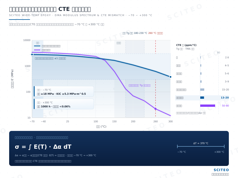
Silicon, aluminium nitride, Kovar, stainless steel, glass-fibre resin substrates and cured epoxy sit at CTE values of roughly 2.6, 4–5, 5–6, 13–17, 15–20 and 50–80 ppm/°C respectively. When dissimilar materials share an interface through a temperature excursion, the difference in contraction becomes a strain differential that accumulates as interfacial shear stress:
σ = ∫ [ E(T) · (α_substrate − α_adhesive) ] dT (integrated from the low-temperature end to the high-temperature end)
Here E(T) is the storage modulus as a function of temperature and α is the coefficient of thermal expansion. The integral points to two levers: lowering CTE shrinks the α term, while widening the modulus plateau flattens the E(T) term. Across an excursion of 370 °C whose two ends demand opposite modulus behaviour, both levers have to be held at the same time. Most selection disputes are really arguments about which of the two should give way, and writing the integral out usually moves the discussion onto concrete numbers.
Flattening the Modulus Spectrum
Conventional epoxy collapses in modulus above its glass transition and climbs steeply again in the deep glassy state, departing from the design window at both ends. A wide-temperature formulation aims to hold storage modulus on a broad, flat plateau from −70 °C to +300 °C, compressing the variation to within one order of magnitude so that interfacial stress stays controllable across the whole range.
There is no single route. Flexible ether linkages and long aliphatic backbones provide chain-segment freedom at low temperature, rigid multifunctional structures preserve dimensional stability at high temperature, and core-shell rubber particles act as a dispersed phase that absorbs local stress concentration. A higher toughener fraction lowers both high-temperature modulus and thermal conductivity, and the curing-agent system shifts the transition and the low-temperature modulus slope at the same time, which is why wide-temperature products are usually segmented by temperature band. Expecting one formulation to run from liquid nitrogen all the way to 1,000 °C is the quickest way to end up short at one end, which is why we ask customers to define the temperature profile before discussing individual numbers.
Fracture Toughness: The Real Bar at the Cold End
Cold-end failure rarely presents as insufficient strength; it presents as a crack that initiates and then propagates without resistance. A base diglycidyl ether of bisphenol A (DGEBA) system cured with an aromatic amine offers fracture toughness around 2.0 MPa·m^0.5 at liquid nitrogen temperature; introducing short-chain flexible chain extenders raises this to the 5.3 MPa·m^0.5 range. That difference decides whether an interface dissipates strain or fractures on the first cool-down.
Core-shell rubber toughening remains effective at low temperature: cavitation inside the particles relieves the hydrostatic pressure generated by volumetric contraction, and the surrounding matrix yields in shear to form plastic shear bands that spread the concentrated stress over a larger volume.
Cold End: Embrittlement and Interfacial Peel from −70 °C to −40 °C
Deep-cryogenic bonding at liquid nitrogen and liquid hydrogen temperatures follows a separate technical route. What matters here is only the stretch a wide-temperature product actually has to cover: −70 °C to −40 °C, which maps to high-latitude outdoor equipment, high-altitude airborne electronics and cold-region service hardware. The difference from deep-cryogenic bonding is not how much colder it gets, but that this stretch has to share one interface with the 300 °C hot end, and the two ends pull the material in opposite directions by nature.
Deep Glassy State and Modulus Rise
As temperature falls, free volume contracts continuously and relaxation times lengthen exponentially in line with Arrhenius or WLF behaviour, so chain segments progressively lose mobility. Below the glass transition the adhesive enters a deep glassy state, storage modulus can reach several times its room-temperature value, and elongation at break collapses. Residual contraction strain can no longer be dissipated through plastic deformation; it appears as interfacial shear stress or as internal stress peaks.
One misreading we correct repeatedly in technical reviews: glass transition temperature is not a usable performance window at low temperature. A room-temperature-rigid epoxy that keeps its modulus flat below the transition and retains enough fracture toughness is often a better cold-end choice than a low-Tg flexible system; what to check is the slope of the modulus curve at the cold end and the fracture toughness value, not whether Tg sits high or low.
Interfacial Peel, Condensation and Hermeticity Failure
Cold-end assemblies often begin to fail at hermeticity. The adhesive layer contracts more than the metal or ceramic substrate, loading the interface in both normal and shear directions. If polar anchoring is inadequate, the adhesive peels away and moisture migrates into the peeled seam, where condensation and frost widen the path further. In hermetic components such as sealed relays, contactors and quartz resonators, and in RF modules, condensation inside the cavity shifts contact resistance and reference frequency immediately. On the rework bench it is common to cut open a part that looks perfect and find a dye-penetrated ingress path at the interface, which is why peel strength ranks alongside fracture toughness as a first-tier cold-end criterion.
Low-Temperature Selection Criteria
Four data sets define cold-end selection: shear strength and its retention at the target temperature, low-temperature fracture toughness, interfacial peel strength, and strength retention after thermal cycling. SCITEO's wide-temperature system pairs a low-modulus stress-buffering formulation with flexible chain segments so that −70 °C extremes and 300 °C long-term service hold in a single formulation, with shear strength at 18 MPa or above at −70 °C and no brittle cracking. Where low-temperature toughness and high rigidity must coexist, the same platform offers a high-modulus thermally conductive grade that keeps an anti-hardening margin at low temperature along a 1.5 W/m·K thermal path.
Hot End: Thermo-Oxidative Aging, Dielectrics and Outgassing from +150 °C to +300 °C
The hot-end constraint on a wide-temperature product does not coincide with that of a dedicated high-temperature adhesive: the formulation must also stay low-shrinkage and low-stress at temperature, otherwise residual stress built up during cure and thermal aging cancels the toughness designed in for the cold end. That was the first boundary we fixed when developing the wide-temperature platform, and it is what separates it from a single-purpose high-temperature product.
Thermo-Oxidative Degradation and Volumetric Expansion
Between 150 °C and 300 °C continuous service, the leading failure modes are thermo-oxidative backbone degradation and oxidation of interfacial polar groups. Volumetric expansion plus the adhesive's own outgassing raises internal pressure inside sealed structures and loads the seal face; for automotive power devices, industrial power modules and military cavities, seal failure typically precedes mechanical failure. The formulation answer is higher bond energy and oxidation stability in the crosslinked network, together with cure shrinkage held below 0.06%.
Dielectric Decay, Ion Migration and Vacuum Outgassing
The electrical side moves in the same direction: higher temperature intensifies polar-molecule motion, raising dielectric loss and lowering volume resistivity. With moisture present, mobile sodium and chloride ions migrate toward the electrodes under the applied field, forming dendrites or altering the local dielectric environment; insertion loss rises and RF metrics drift while mechanical strength may still pass. Module-level and military-grade selection therefore holds mobile ion content in the 10 ppm range.
Vacuum and cleanroom applications add an outgassing constraint. Space optics, detectors and high-vacuum chambers are screened to ASTM E595 at 125 °C for 24 hours at better than 7×10⁻³ Pa, comparing total mass loss and collected volatile condensable materials against the industry screening lines of TML ≤1.0% and CVCM ≤0.1%. SCITEO's wide-temperature system holds measured CVCM below 0.005%. With vacuum-chamber customers this figure tends to come up earlier than room-temperature shear strength.
Boundary Handover at Both Ends of the Temperature Profile
Above 300 °C, conventional polymer networks enter irreversible thermo-oxidative degradation, and the interface material must switch to an ultra-high-temperature formulation route: SCITEO's ultra-high-temperature grade takes over structural anchoring and electrical insulation from 300 °C to 1,000 °C, where insulation is usually the first metric to fail rather than mechanical strength. The opposite end has its own route: interfaces at liquid nitrogen temperature and down to the −225 °C class rely mainly on low-modulus stress buffering and high fracture toughness, sharing formulation logic with the −70 °C to +300 °C band while weighting the metrics differently. SCITEO covers all three bands under one validation system, so customers do not have to switch supplier conventions while they are still defining their temperature profile.
Validation: Process Shock, Thermal Shock and Thermal Cycling
Capability in a wide-temperature material has to be proven through three separate test families; substituting one for another leads to wrong conclusions. Their ramp rates, load amplitudes and failure modes all differ, so we take them one at a time.
Process Thermal Shock: 260 °C Peak Reflow with Rework Stacked On Top
In PCBA manufacturing, the adhesive must pass reflow undamaged after dispensing and cure. Peak-zone temperature rises to roughly 260 °C within tens of seconds; ordinary adhesives lose storage modulus abruptly above their transition and, under hot-air turbulence and conveyor vibration, the unsupported components drift or fall off. If CTE is too high, the pulling force from volumetric expansion lifts small pads outright. Double-sided assembly and rework mean the bondline sees more than one reflow, so the engineering margin should be set at three or more excursions; SCITEO's wide-temperature system passes three or more 260 °C peak reflow cycles without micro-cracking, delamination or peel.
GJB 150.5A Thermal Shock: Fracture Toughness under Transient Thermal Gradients
Thermal shock describes an abrupt change in ambient air temperature, usually defined by a rate above 10 °C/min. GJB 150.5A uses a dual-bath or dual-chamber arrangement that transfers the specimen rapidly between cold and hot zones, with transfer time typically specified within one minute. The loading profile combines an extremely high ramp rate with a very large single-cycle amplitude, which directly amplifies CTE mismatch at the interface and tests whether the material fractures or shatters immediately under a large transient thermal gradient rather than how it fatigues. In SCITEO's military thermal shock retests, differences in transfer time on the minute scale change where and how the interface fractures.
AEC-Q and JESD22-A104 Thermal Cycling: Fatigue Initiation and Propagation
Thermal cycling ramps at roughly ten-plus degrees Celsius per minute with dwell times at both extremes. JEDEC JESD22-A104F.01 is the most widely used cycling method for automotive electronics, and AEC-Q100 (Rev-J) divides devices by ambient operating temperature: Grade 1 covers −40 °C to +125 °C, while Grade 0 extends to −40 °C to +150 °C. With typical activation energies of 0.4 to 0.7 eV, Arrhenius acceleration multiplies the rate constant of most failure mechanisms by roughly two to three when the peak moves from 125 °C to 150 °C, which is the physical reason Grade 0 places extra demands on interfacial materials. Cycling exercises fatigue-crack initiation and propagation, and failures usually appear late in the campaign rather than on the first excursion; beyond the standard condition, SCITEO extends cycling to 1,500 excursions and still holds at least 95% shear strength retention after TC1500.
Damp Heat and Salt Fog as Underestimated Superimposed Variables
Temperature alone does not cover real service. Damp-heat bias drives hydrolytic bond scission at the interface, degrading insulation resistance and mechanical strength together; automotive and industrial modules are generally screened through a 1,000-hour steady-state temperature humidity bias life test, commonly referred to as the 85/85 condition, and coastal or outdoor hardware adds salt fog and fungal exposure. SCITEO tightens the damp-heat duration to 1,500 hours as well, holds at least 90% shear strength retention after THS1500 and lists mobile ion content as a parallel deliverable. A duty cycle is only fully described when the temperature profile and its extremes, the humidity or vacuum condition, and the cycle count with dwell time are read together.
Device-Level Interface Requirements across Selected Advanced Segments
The first four sections cover the general physics and the validation framework. On a real device the same parameters carry very different weight, so the sections below pick a handful of representative cases by the shape of their temperature profile and focus on how the interface material should be chosen. Deeper packaging structures and line processes have their own articles on this site; only what is directly relevant to wide-temperature selection is kept here.
Edge AI and AIoT Host Processor Packaging
Edge AI host processors are moving from single-core control to heterogeneous multi-core hosting with on-device large-model inference. NPU compute has climbed from a few TOPS into the 30 to 50 TOPS class, memory is migrating from LPDDR4X to LPDDR5X with LPDDR6 starting to appear on newer platforms, and package formats are shifting from LGA toward FCBGA with memory stacking. The interfacial load changes with them: CTE mismatch between die and substrate is amplified by the larger package footprint, warpage in stacked structures worsens at reflow peak, and automotive and industrial use demand long-term stability from −40 °C to +105 °C and up to +125 °C.
Failure in these packages is composite. Manufacturing exposes the bondline to 260 °C peak reflow and double-sided rework; service exposes it to thousands of thermal cycles, and the two stages load the material in different directions at different rates. SCITEO's wide-temperature system uses cure shrinkage below 0.06% and low-modulus stress buffering to spread the stress concentration at die corners and bump roots across the whole interface, while the high-Tg backbone keeps modulus margin through the 260 °C peak. When edge compute is added as a separate co-processor module, the heat flux from its high-bandwidth memory and accelerator is far above that of a conventional host, and both the thermal interface and the mechanical fixation must hold thermal resistance stable between −40 °C and +125 °C.
For the packaging house and the system integrator, yield and field failure rate come down to whether interface behaviour is predictable. Corner stress concentration as die area grows, the warpage magnitude of stacked structures, and alignment and thermal resistance after cycling are all governed by four variables: modulus spectrum, CTE, cure shrinkage and interfacial void fraction. SCITEO delivers those four data sets against a device's actual temperature profile, turning the interface from a variable that can only be screened after the fact into a design input.
High-Reliability Military Electronic Components
The interface brief in high-reliability electronic systems comes down to one thing: keeping electrical switching, time-frequency references and energy-storage nodes stable inside a sealed cavity for a decade or more. The components that carry this brief include sealed relays, solid-state relays and contactors, crystal resonators, tantalum capacitors and inertial devices, along with multi-chip hybrid assemblies. Their common constraints are miniaturisation, hermetic packaging and maintenance-free life beyond ten years, so the interface material carries sealing, insulation and mechanical anchoring at once.
Failure concentrates in three places: potting fixation of the coil and magnetic circuit, rigid support of crystal resonators and inertial devices, and termination bonding at tantalum capacitor nodes. GJB 150.5A thermal shock is normally specified with transfer time within one minute, so the bondline must survive abrupt transitions from −55 °C to +150 °C without cracking or debonding. Outgassing control and hermeticity screening form one chain for these parts: helium fine-leak testing per GJB 548 and MIL-STD-883 Method 1014, internal water vapor control per Method 1018, and condensable volatiles below the 0.1% screening line (SCITEO's wide-temperature system measures below 0.005%), because deposited material lands on contacts and resonator bodies and changes contact resistance and reference frequency. Crystal resonators and inertial devices are especially sensitive to the modulus-versus-temperature curve, where modulus drift translates directly into frequency offset and zero-point drift; SCITEO addresses that path with a low-modulus stress-buffering formulation and modulus-plateau design that keeps full-range drift inside the device's frequency-offset budget.
Wide-Area IoT and RF Modules
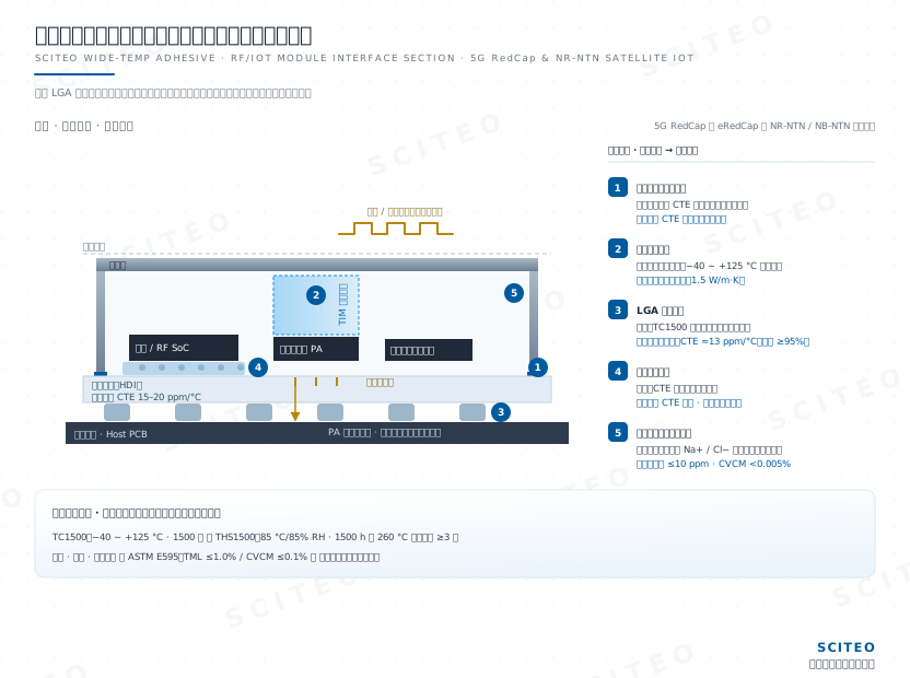
Wide-area IoT and RF modules ship mainly in LGA, LCC and M.2 formats, integrating baseband, RF front end, power amplifier, shielding can and a multi-constellation positioning receiver; some platforms merge an NPU with the baseband in the same package, so connectivity and on-device inference share one thermal path. Two directions press at once: 5G RedCap has entered volume ramp-up, with connections in China moving toward the hundred-million mark, and eRedCap, frozen in Release 18, has entered commercial deployment; the module has to hold uplink dynamic range on a 20 MHz-class carrier, and eRedCap narrows the baseband data channel further to the 5 MHz step to buy back cost and power. At the same time NR-NTN together with NB-NTN extends connectivity beyond terrestrial coverage, where one antenna has to serve both terrestrial and satellite bands, further compressing the power budget and thermal headroom of the RF front end.
Thermal and humidity thresholds rise with it. Industrial-grade modules typically ask only for −40 °C to +85 °C, and automotive-grade parts extend to −40 °C to +105 °C with damp heat and vibration added, but that is an entry condition rather than the bar: once a module is reviewed under the multi-chip-module regime, thermal cycling and damp-heat bias tighten at the same time. The interface material has to hold shear strength above 95% after TC1500 (−40 °C to +125 °C, 1,500 excursions) and above 90% after THS1500 (85 °C/85% RH, 1,500 hours) before it qualifies as a front-loading supply-chain candidate. Production lines running into the tens of millions of units per month also require adhesives matched to high-speed dispensing and fast cure, so the process window matters as much as the datasheet.
Three failure modes dominate at this scale: solder-joint fatigue between the shielding can and the board driven by CTE mismatch; loss of the thermal path near the power amplifier during thermal cycling, which reduces output power; and electrochemical migration (ECM) under damp-heat bias that shifts RF metrics. At this scale SCITEO combines structural fixation, thermal path and ion barrier in one low-ion wide-temperature formulation, holds mobile ion content in the 10 ppm range, and treats strength retention and insulation resistance after TC1500 and THS1500 as parallel deliverables.
Laser Processing and Optoelectronic Devices
High-power lasers, optical lens assemblies, optical modules and optical engines are among the most interface-dense assemblies in manufacturing. Pluggable modules have moved to 1.6T and are in volume delivery, near-package optics (NPO) has completed 800G/1.6T batch sampling and pilot deployment, and co-packaged optics (CPO) is in production preparation; with optical path tolerance compressed into the sub-micron range, cure shrinkage in the bondline moves the coupling position directly, and every 0.1% of shrinkage is amplified into micron-scale offset across a millimetre-scale span. The interfaces that fix laser pump sources to crystals and fibres carry high heat flux and thermal cycling at the same time: the bondline has to conduct heat away and still hold a sub-micron coupling position over life. Packaging is also shifting toward glass substrates and through-glass vias (TGV), where glass CTE can be tuned to 3–9 ppm/°C while organic carriers remain at 17–20 ppm/°C; mixing the two multiplies the number of interfaces and the expansion mismatch together, making warpage and alignment first-order constraints.
These applications demand tighter control of cure shrinkage, modulus and dimensional stability across temperature than ordinary structural bonding. For optoelectronic packaging SCITEO provides low-CTE optical formulations whose bondline CTE can be matched into the 13–20 ppm/°C band, closely matched to glass-fibre composite carriers and forming a controlled expansion gradient against glass substrates, compressing alignment drift at its source; combined with low cure shrinkage and low-modulus stress buffering, they cover optical engine alignment, pump source fixation and lens assembly bonding, with full-range modulus linearity confirmed from the DMA curve. Inertial and MEMS sensor packaging calls for the same capability: when a device looks intact but its output drifts, the cause is usually nonlinear modulus combined with CTE mismatch.
Wide-Temperature Selection Quick Reference
The table compresses the failure physics above into executable selection criteria for review:
| Service Segment | Typical Failure Mode | Key Criteria | SCITEO Direction |
|---|---|---|---|
| Low-temperature service (−70 °C to −40 °C) | Deep glassy brittle fracture, interfacial peel, condensation ingress | Low-temperature shear strength, low-temperature fracture toughness, peel strength | Low-modulus stress-buffering grade (−70 °C class) |
| Continuous high-temperature service (150 °C to 300 °C) | Thermo-oxidative degradation, expansion, dielectric decay | Long-term aging retention, transition temperature, cure shrinkage | Wide-temperature high-crosslink backbone grade |
| Process shock (260 °C reflow) | Softening flow, component drift, pad lift | Reflow cycle tolerance, cure shrinkage | High-Tg low-shrinkage grade |
| Thermal shock (military) | Brittle fracture under transient gradients | Transfer time, low-temperature fracture toughness, interface integrity | Wide-temperature toughened series |
| Thermal cycling (automotive) | Late-cycle fatigue crack initiation and propagation | TC1500 shear retention, interfacial void fraction | Automotive wide-temperature series |
| Damp heat and ion migration | Hydrolytic scission, insulation loss, RF metric drift | THS1500 retention, mobile ion content | Low-ion wide-temperature series |
| Sub-micron optoelectronic alignment | Cure shrinkage and CTE mismatch shifting the optical axis | Cure shrinkage, bondline CTE 13–20 ppm/°C, modulus linearity | Low-CTE low-shrinkage optical grade |
Opposite Pulls, Margin Kept in the Middle of the Profile
The hard part of wide-temperature selection is not pushing one end to an extreme, but making the −70 °C and 300 °C ends hold on the same interface at once. The cold end has to flatten the modulus rise and build up fracture toughness, while the hot end has to hold bond energy, oxidation stability and volumetric shrinkage together. The two demand opposite things, and any single-point optimisation is paid for at the other end. On the review table the checkable items are the same few data sets: the DMA modulus curve across the range, the TMA CTE curve, shear retention after thermal cycling and damp-heat bias, and mobile ion and condensable volatile content.
SCITEO Advanced Materials builds on a wide-temperature epoxy platform that converges low-temperature toughening, high-Tg backbone design and low-shrinkage control into one validation flow, and supports selection conclusions with military thermal shock, automotive thermal cycling, 260 °C reflow tolerance and vacuum outgassing data. That validation framework is not tied to a particular device format: any interface falling inside the −70 °C to +300 °C profile can be assessed against the same data.
This article is SCITEO Advanced Materials original technical content; unauthorized reproduction is prohibited.
Appendix: Process & Engineering Adhesive FAQ Index
How do wide-temperature adhesives divide the work with dedicated low-temperature and high-temperature adhesives?
The difference is not the name on the formulation but the shape of the temperature profile. A duty cycle that only exercises the cold end and tops out a little above 100 °C belongs to a low-temperature adhesive, which can spend its entire design margin on chain-segment freedom and fracture toughness without reserving bond-energy headroom for a hot crosslinked network. A duty cycle that stays above 150 °C and rarely sees deep cold belongs to a high-temperature adhesive, where the focus is oxidation stability, high-temperature modulus and outgassing control. A wide-temperature adhesive has to handle a single interface pulled from both ends: the cold end wants a flat modulus and ample toughness, the hot end wants a rigid, shrinkage-controlled network, and the two orientations are opposite, so the only place to find a joint feasible region is the middle of the profile. If a device pushes against the material boundary at both ends, review it as a wide-temperature adhesive; if one end is effectively idle, a narrow-band product will usually take the metrics further.
Why can a wide-temperature adhesive not be selected from its two endpoint ratings alone?
The two endpoints answer what the material can survive, not whether the interface survives with it. Three linked quantities decide service life: the flatness of the modulus spectrum across the whole temperature profile, the CTE mismatch against dissimilar substrates, and the strength retained after thermal aging and thermal cycling. Take a product rated −70 °C to 300 °C whose modulus rises several times at low temperature: the contraction strain has nowhere to dissipate, and a crack initiates inside the bondline or at the interface on the first cool-down. Reverse the case, with a flat modulus but insufficient fracture toughness, and the same interface fails late in cycling. A selection file should carry the DMA modulus curve, the TMA CTE curve and post-cycling shear retention together; SCITEO's delivery format merges those three with shear retention after TC1500 and THS1500 into a single interface data set, and with any one of them missing the fit for the duty cycle stays unresolved.
At −70 °C, why can a higher glass transition temperature actually be the better choice?
Glass transition temperature describes where chain-segment motion is frozen or unfrozen; it governs deformation behaviour, not whether a crack can be arrested. The fatal low-temperature failure is a crack that initiates and propagates without resistance, and fracture toughness measures that resistance. A room-temperature-rigid epoxy that keeps its modulus flat below the transition and retains enough low-temperature fracture toughness is often a better cold-end choice than a low-Tg flexible system, whose modulus rises sharply as it cools and which loses usable performance earlier. Treating the transition temperature as a performance window is the most common misreading in cold-end selection; the data to check are the slope of the modulus curve at the cold end and the fracture toughness value.
AEC-Q100 Grade 0 and Grade 1 differ by only 25 °C. Why does that matter so much for interfacial materials?
Under Arrhenius acceleration, 25 °C is a multiplier rather than a rounding error. Grade 1 covers −40 °C to +125 °C and Grade 0 extends to −40 °C to +150 °C, the latter addressing engine control units, on-board chargers and DC-DC converters in powertrain and power-conversion positions. With typical activation energies of 0.4 to 0.7 eV, raising the peak from 125 °C to 150 °C multiplies the rate constant of most failure mechanisms by roughly two to three, and equivalent life shortens accordingly. The higher cycling endpoint also amplifies the shear stress accumulated from CTE mismatch, so fatigue cracks that appear only late in a Grade 1 campaign initiate earlier at Grade 0. Qualification has to land directly on the Grade 0 profile: shear retention and interfacial void fraction read together, and Grade 1 conclusions do not carry over.
In cellular IoT modules and satellite IoT terminals under combined damp heat and thermal cycling, why is ion migration more critical than strength decay?
A module is a dense interconnect structure in which baseband, RF front end, power amplifier and a high-precision positioning receiver share one package, with interfacial gaps down to the micron scale. Under damp-heat bias, moisture migrates along the interface and mobile sodium and chloride ions travel toward the electrodes under the applied field, forming dendrites or altering the local dielectric environment. The visible result is rising insertion loss, drifting RF metrics and falling insulation resistance, while the adhesive shear strength may still pass its limit. Automotive-grade modules are reviewed under the multi-chip-module regime, which tightens cycling and damp heat at the same time, so shear retention after TC1500, strength and insulation retention after THS1500, and mobile ion content have to be read as three parallel criteria; that is what covers this failure path.
For sealed military relays, solid-state relays and contactors, and quartz resonators, why do GJB 150.5A thermal shock and low outgassing data come first?
The interface in these components carries sealing, insulation and mechanical anchoring at once, and it serves under abrupt transitions between −55 °C and +150 °C. GJB 150.5A defines thermal shock by a rate above 10 °C/min and normally specifies transfer time within one minute, so the test asks whether the bondline fractures or debonds under an extreme transient gradient rather than how it fatigues. At the same time, vacuum, radiation and a sealed cavity require low outgassing: condensable volatiles below the 0.1% industry screening line (SCITEO's wide-temperature system measures below 0.005%), otherwise deposited material lands on contacts and resonator bodies and changes contact resistance and reference frequency directly; seal integrity itself is verified on the GJB 548 and MIL-STD-883 Method 1014 fine-leak basis, in step with the interface review.
As optical modules and engines move to sub-micron alignment, why do cure shrinkage and CTE become decisive?
An optical engine compresses path tolerance into the sub-micron range, so cure shrinkage in the bondline moves the coupling position directly: every 0.1% of shrinkage is amplified into micron-scale offset across a millimetre-scale span. CTE matters just as much, because glass-fibre composite and organic carriers sit at 17–20 ppm/°C while glass substrates can go as low as 3–9 ppm/°C; the adhesive has to sit on that spectrum as a controlled expansion gradient, or alignment cannot be met at both ends of the cycle at once. Cure shrinkage below 0.06%, a bondline CTE inside 13–20 ppm/°C, and a DMA curve that stays linear across the range: with those three in place, sub-micron alignment drift becomes a discussion worth having.
In coil potting for sealed relays and contactors, why does insulation degrade before mechanical cracking under thermal shock?
Potting distributes stress differently from structural bonding. The coil and magnetic circuit are fully encapsulated, so on cool-down the adhesive layer is constrained by the metal frame and strain concentrates at geometric transitions such as the inter-turn windings and the lead-out root. If low-temperature modulus rises too quickly, micro-cracks propagate along the inter-turn insulation, so insulation resistance and withstand voltage drop first while appearance and mechanical strength can still pass for a long time. The review order for such parts is therefore the low-temperature modulus slope, insulation resistance retention after cycling and cure shrinkage, not room-temperature shear strength; SCITEO's wide-temperature system flattens the modulus spectrum to hold the low-temperature modulus rise within a controlled range and keeps cure shrinkage below 0.06%.