Why High-Temperature Adhesives Fail: Interface Diagnosis and Selection for High-End Sensors and Quantum Measurement at 300-500 °C
SCITEO Engineering Methodology: Grounded in Physics of Failure (PoF), bridging main-chain thermo-oxidative scission, storage modulus collapse above Tg, and CTE shear fatigue to govern interfacial service lifetimes and forward reliability principles through comprehensive TGA/DMA/TMA empirical spectra.
Abstract
High-temperature adhesives rarely fail outside their rated temperature, and rarely for one reason. The failure usually lands on the interface where temperature, time and media overlap: an adhesive rated to 200 °C debonds at 180 °C, and one rated to 300 °C carbonizes after an hour at 280 °C. The number on the datasheet is not wrong. The mistake is a selection habit that treats the rated temperature as the only admission gate. What decides how long an interface survives is whether the glass transition temperature (Tg), main-chain bond energy and coefficient of thermal expansion (CTE) actually line up with the duty cycle. Following the physics-of-failure route, this article separates four dominant mechanisms: modulus collapse and creep accumulation above Tg, main-chain thermo-oxidative degradation and carbonization, CTE-driven interfacial shear fatigue, and the voids or delamination caused by moisture vaporization and outgassing. It then sets out how to read root cause from field symptoms, how to take evidence from the three governing curves (TGA, DMA and TMA), and how to test all of it against extreme interfaces in quantum measurement, cooled infrared detection, automotive temperature and gas sensing, and high-power-density drive. SCITEO Advanced Materials covers this window with a 190-240 °C Tg backbone, room-temperature shear above 30 MPa, at least 80% shear retention after 500 hours at 250 °C, and CTE as low as 7.5 ppm/°C.
Get the selection sequence right and most of the risk is removed at the drawing stage: fix the temperature profile and its time weighting first, verify post-aging strength retention and CTE matching second, and read the nominal temperature rating last.
Core Parameter Comparison
The table below compresses the selection basis into verifiable data points and pairs each metric with the failure signature it explains and the test that captures it. SCITEO systems are benchmarked against conventional high-temperature adhesives:
| Evaluation Dimension | SCITEO | Industry Standard | Failure Signature & Evidence |
|---|---|---|---|
| Long-term temperature limit (portfolio envelope) | 300-500 °C | 150-200 °C | Carbonized, pulverized after aging; TGA |
| Short-term peak temperature | 600 °C class | 250-300 °C | Transient deformation, blistering; thermal shock test |
| Tg (glass transition temperature) | 190-240 °C | 80-150 °C | Displacement, tacky bondline at temperature; DMA inflection |
| Storage modulus platform (below Tg) | 10-25 GPa | 3-5 GPa | Load-bearing shift, stress relaxation; DMA plateau height |
| Room-temperature shear strength | ≥30 MPa | 10-20 MPa | Interfacial slip; GB/T 7124 |
| Shear retention at 250 °C/500 h | ≥80% | Below 50% | Post-aging strength decay; JEDEC JESD22-A103 |
| Condition after 300 °C/48 h | No embrittlement, no carbonization | Carbonized, pulverized | Chalking, falling insulation; heat aging + shear retest |
| CTE (below Tg) | 7.5-25 ppm/°C | 40-60 ppm/°C | Interfacial disbond, substrate cracking; TMA |
| T-peel strength | ≥6 N/mm | 1-2 N/mm | Edge lift and delamination; GB/T 2791 |
| Cure shrinkage | <0.5% | 1-3% | Optical alignment drift; ISO 2577 |
| Water absorption, boiling water 8 h | 0.0033% | 0.5-1% | Popcorn-effect blistering; GB/T 1034 |
The Physics of Failure: From Modulus Collapse to Interfacial Shear Fatigue
High-temperature adhesive failure comes down to main-chain bond energy competing with environmental thermal energy over time. Engineers who have run a few failure reviews know the pattern: sort the returned parts by symptom, and almost all of them collapse into four paths. Those paths rarely act alone; they tend to run together and reinforce one another. Only when the boundary of each path is pinned down can selection move from trial-and-error to design-for-reliability.
Modulus Collapse Above Tg: Undecomposed, but No Longer Rigid
Tg is the temperature window in which polymer chain segments shift from frozen to mobile. Its engineering meaning is direct: above Tg the storage modulus (E') falls rapidly across a narrow band, and a typical high-temperature epoxy drops from the GPa range to the 10 MPa range. The chemical structure has not yet decomposed and the TGA curve shows no meaningful mass loss, but rigid support is already gone.
Modulus collapse leaves two mechanical debts. Creep compliance climbs, so under sustained load the adhesive flows viscously and irreversibly, and interfacial displacement moves from elastically recoverable to plastically locked. Stress relaxation accelerates at the same time, transferring thermomechanical load the adhesive used to carry onto leads, bond joints and solder joints. On a device that was never overloaded, this shows up as displacement, audible noise or signal drift.
Engineering practice calls for 20-30 °C of Tg margin on any load-bearing interface, and that margin must be confirmed from the inflection point of the DMA curve rather than a single reported number. One misread is common: Tg measures when deformation behavior unlocks, while the temperature limit measures how long main-chain bonds survive under temperature and time together. They are two different quantities and each needs its own evidence.
Thermo-Oxidative Degradation: Main-Chain Scission, Mass Loss and Carbonization
In an oxygen-bearing high-temperature environment, carbon-carbon and carbon-nitrogen bonds face continuous free-radical attack. Chains scission, side groups detach, and the residue is predominantly amorphous carbon. Carbon conducts. Once that carbon phase forms a continuous path inside the bondline, a dielectric that was doing electrical isolation can lose its insulating function within tens of hours. What makes this failure class dangerous is that it is gradual: it accumulates with temperature and time instead of arriving as a single breakdown event, so a one-shot room-temperature withstand test will never find it. Volume resistivity has to be logged at the target temperature over time.
Screening usually starts with TGA. The mass-loss step marks the band where main-chain decomposition becomes significant, and the 5% mass-loss temperature is the standard gate. If mass loss exceeds 5% inside the target window, micro-pores form and mechanical strength and breakdown voltage fall together. Color change deserves separate treatment: amine curing agents oxidize and darken at temperature on their own, so as long as shear strength holds, a darker bondline is not a failure. The verdict belongs to post-aging mechanical and electrical retesting.
Above roughly 400-500 °C of continuous service, the chemical boundary of conventional organic systems is reached, and the route forward is to move to inorganic systems built on high-bond-energy backbones such as Si-O-Al, removing the carbon skeleton at the chemistry level. That path is carried by the SCITEO ultra-high-temperature product line. This article stays inside the 300-500 °C window of organic and semi-inorganic systems, where precision measurement instruments, high-end sensors and high-power-density drive units concentrate.
CTE Mismatch: Interfacial Shear Fatigue Accumulates from Thermal Strain
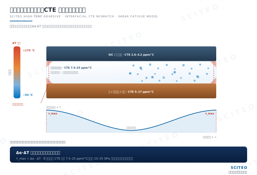
When dissimilar materials share an interface, they do not contract in step. The gap shows up in a few common values: silicon near 2.6 ppm/°C, silicon carbide near 4.0-4.5 ppm/°C, Kovar and alumina ceramic in the 5-8 ppm/°C band, copper near 17 ppm/°C, and fused quartz down near 0.5 ppm/°C. Unfilled rigid epoxies, by contrast, generally exceed 50 ppm/°C. Multiply that difference by the temperature swing and by the storage modulus of the adhesive at that temperature, and you have the shear stress the interface actually carries.
The failure signatures are specific. A clean break at the interface with bare substrate is adhesive failure, usually from CTE mismatch combined with insufficient surface preparation. A break inside the bondline with a crack network is cohesive failure, usually from main-chain degradation or insufficient crosslink density. Large interfaces and high-cycle thermal excursions amplify both, and corners and edges are where stress concentration appears first.
Lowering CTE depends on the filler system and the crosslinked network working together: a rigid backbone holds dimensional stability at temperature, a high-volume-fraction inorganic filler pulls bulk expansion toward the ceramic and metal side, and the coupling agent decides whether stress transfers cleanly from resin to filler to substrate. Across its potting and bonding systems, SCITEO holds the linear expansion coefficient below 25 ppm/°C, brings 400 °C-plus systems down to 7.5 ppm/°C, and forms low-mismatch interfaces against ceramic, glass and Si/SiC substrates.
Outgassing, Moisture Vaporization and Electrochemical Migration: Three Parallel Branches
Three further branches cause losses that are often as large as mechanical failure.
Outgassing occurs during ramp-up and aging. Small molecules released from the matrix leave voids behind, and a void is three defect sources at once: a crack initiation site mechanically, a thermal-resistance spike thermally, and a partial-discharge inception point electrically. Vacuum and cleanroom duty is especially sensitive, which is why ASTM E595 constrains total mass loss (TML) and collected volatile condensable materials (CVCM). Condensate on chamber walls, probes and optical windows turns into yield loss that is very hard to trace back.
Moisture vaporization is a different mechanism. Through its free-volume network, the adhesive absorbs water in humid environments. If that moisture is not driven out before the assembly enters a peak-temperature excursion, it vaporizes in seconds and generates vapor pressure that lifts the interface into blistering and delamination, the familiar popcorn effect. IPC/JEDEC J-STD-020 governs this with a moisture sensitivity level (MSL), which sets floor life and the bake required before peak temperature. The lower the water absorption of the interface material, the narrower this risk path becomes. SCITEO high-temperature systems measure 0.0033% water absorption in boiling water per GB/T 1034, which pushes the moisture source well down.
Electrochemical migration requires moisture, an electric field and mobile ions at the same time. Sodium and chloride ions migrate toward the electrodes, grow dendrites or alter the local dielectric environment, showing up as falling insulation resistance, rising insertion loss and drifting signal levels while shear strength remains within specification. For any high-temperature, high-humidity duty, mobile ion content and insulation retention after thermal cycling must be reviewed together rather than treating mechanical data as sufficient.
Failure Fingerprints: Reading Root Cause from Field Symptoms
Failure analysis earns its keep when it maps a field symptom precisely onto a material mechanism. The table below pairs common symptoms with the dominant mechanism, the key metric and the test that reproduces it, so engineers can use it directly during a failure review:
| Field Symptom | Dominant Mechanism | Key Metric | Reproduction Test |
|---|---|---|---|
| Component shift at temperature, tacky or stringy bondline | Modulus collapse and creep above Tg | DMA curve, operating temperature versus Tg margin | Sustained high-temperature load test |
| Darkened adhesive with unchanged strength | Cure-agent oxidation, not failure | Post-aging shear retest | Heat aging plus shear retest |
| Surface chalking, powdering, strength near zero | Main-chain thermo-oxidative degradation and carbonization | TGA mass-loss step, 5% mass-loss temperature | Long-term aging at 300-400 °C |
| Clean interface separation, bare substrate | CTE mismatch plus insufficient surface preparation | CTE by TMA, interfacial peel strength | Thermal shock and temperature cycling |
| Internal cracks, voids, blistering | Moisture vaporization and outgassing | Water absorption, CVCM, MSL classification | Boiling water and damp heat plus peak temperature |
| Falling insulation resistance, lower PDIV | Electrochemical migration and partial-discharge erosion | Mobile ion content, partial-discharge inception voltage | 85/85 bias plus partial-discharge measurement |
| Blackened interface with dendrites | Conductive carbonization path | Volume resistivity versus temperature | High-temperature volume resistivity test |
| Optical element shift, alignment drift | Modulus collapse, stress relaxation and cure shrinkage under isothermal and across-temperature duty | Modulus-platform retention, Tg margin, cure shrinkage | Isothermal and across-temperature cycling plus alignment remeasurement |
| Rising vacuum cavity pressure, slower cool-down | Adhesive outgassing and desorbed moisture release | TML/CVCM, mass loss after vacuum bake | Vacuum bake plus pressure-rise method |
One symptom can map to several mechanisms. Adhesive versus cohesive failure separates by fracture location, carbonization versus simple darkening separates by mass loss and strength data, and voiding versus moisture vaporization separates by water absorption and CVCM. The endpoint of diagnosis is a set of test conditions another engineer can reproduce, which is what gives formulation work a verification target. SCITEO files its failure reviews under the same convention, so cross-lot comparisons do not need the terminology renegotiated.
Evidence Discipline: Temperature Profile, Time Weighting and Three Curves
Three Temperatures Must Be Accounted Separately
Unless stated otherwise, the temperature range on a TDS refers to short-term exposure. Three temperatures must be recorded separately: short-term peak temperature for processes lasting minutes to tens of minutes, such as reflow, bake and transient thermal shock; long-term operating temperature for the sum of ambient temperature and self-heating across the service life; and long-term aging temperature as the accelerated-test condition used to expose decay trends within an acceptable timeframe.
Their weights differ. Peak temperature tests transient resistance to deformation and Tg margin; long-term operating temperature tests chemical stability of the main chain; aging temperature tests whether the material retains strength as temperature integrates over time. For SCITEO high-temperature systems, shear retention stays at or above 80% after 500 hours at 250 °C, and parts remain unembrittled with no carbonization after 48 hours at 300 °C. Those two datasets cover the long-term operating and long-term aging boundaries respectively, and they deserve more scrutiny during review than a nominal temperature rating.
Each Curve Answers One Question
TGA defines the chemical boundary. The mass-loss step marks where main-chain decomposition begins, the 5% mass-loss temperature is the standard gate, and the curve also supports batch-to-batch thermal consistency checks.
DMA defines the mechanical boundary. The rate at which storage modulus falls with temperature, the location of the Tg inflection, and the height of the glassy plateau together determine whether the bondline can still carry load at temperature. On a load-bearing interface the height of the glassy plateau is a metric in its own right, which is why the storage modulus platform is tracked separately here. Read the shape of the curve rather than a single Tg value: the same material can differ by more than ten degrees between DSC and DMA, so a selection file must state the method and the heating rate. Without that, data from different suppliers cannot be compared.
TMA defines the stress boundary. CTE normally shows two different slopes on either side of Tg, and interfacial stress is governed mainly by the segment below Tg. For large-area bonds or heterogeneous packages, bondline thickness and cure shrinkage also belong in the assessment, so that a local stress concentration fails first rather than the assembly.
The Limits of Accelerated Aging and Extrapolation
Heat aging is fundamentally temperature integrated over time. Arrhenius acceleration can compress the test schedule, but extrapolation has one precondition: the failure mechanism must not switch tracks. At least three temperature points are required, all with a consistent failure mechanism; the ramp must not cross a phase-transition or decomposition inflection; and the extrapolated endpoint still needs real failure data behind it. Extrapolating tens of thousands of hours from a single short-term point produces a number with no engineering meaning. SCITEO collects heat-aging data in sets along a temperature profile and confirms the mechanism has not switched before extrapolating.
Functional metrics must be retested after aging. Visual inspection only catches carbonization, cracking and obvious discoloration, while modulus loss, interface weakening and insulation decay typically occur while the sample still looks intact. A defensible acceptance check retests shear strength, peel strength and insulation resistance after aging, and reports retention against the initial values.
Extreme-Duty Validation: Failure Boundaries Across Selected Interfaces
High-end high-temperature duty rarely tests one property at a time, and temperature, outgassing, insulation and structural stress usually arrive together. The interface classes below draw on a portion of the interface experience SCITEO has accumulated in real service.
Alkali Vapor Cells and Diamond Color Centers in Quantum Measurement
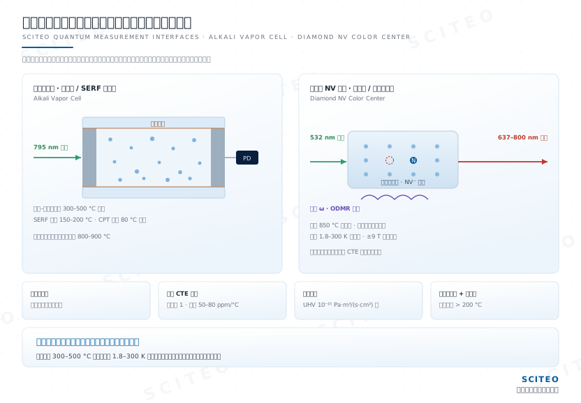
Quantum measurement uses atoms or solid-state spins as the measurement reference and is known in industry as quantum precision measurement. Today's routes split into two families. The first is the alkali vapor cell family: coherent population trapping chip-scale atomic clocks, optically pumped and SERF magnetometers, and nuclear magnetic resonance gyroscopes. The second is the room-temperature solid-state color center family: diamond nitrogen-vacancy magnetometers, quantum microscopes, quantum scanning probes and electron paramagnetic resonance spectrometers. The first gate on whether an interface can ship is not operating temperature but process temperature: cells are anodically bonded between glass and silicon at 300-500 °C; an ultra-high-vacuum chamber receives a 400 °C class whole-body bake to drive hydrogen outgassing down to the 10⁻¹⁵ Pa·m³/(s·cm²) level, with vacuum-furnace routes pushing stainless components to 500 °C; laser desorption of the alkali dispenser reaches 800-900 °C locally; and diamond color-center fabrication passes through an 850 °C class anneal. Operating temperature is only the second gate: a CPT cell must be held above 80 °C to build usable alkali vapor pressure, SERF operation drives the cell into the 150-200 °C band, and diamond quantum microscopes and scanning probes must hold optical alignment and spin coherence across 1.8-300 K and under magnetic fields up to 9 T.
Temperature is only the entry ticket. The real constraint sits in four physical quantities that get amplified at the same time.
Inside a ±9 T bias field and the magnetic shield, material susceptibility turns straight into a signal problem. Any ferromagnetic or high-susceptibility constituent in the adhesive injects magnetic noise into the probe near field and raises the noise floor of femtotesla-class magnetometers and nanotesla-class color-center magnetometers.
Microwave heating is unavoidable, because optically detected magnetic resonance excites the color center with microwaves. In practice the diamond is fixed to a ceramic substrate with a high-thermal-conductivity adhesive and shares one cavity with the microstrip microwave antenna, the optical filter and the photodetector, so the adhesive must deliver low microwave loss, high thermal conductivity and tolerance for local temperature rise at once. At high microwave power the antenna root can exceed 200 °C, and dielectric-loss heating shifts the ODMR resonance, producing zero-point drift and linewidth broadening.
Ultra-low expansion matching is another hard constraint. Diamond sits at roughly 1 ppm/°C, sapphire at 5-6 ppm/°C and optical glass at 3-8 ppm/°C, while conventional epoxies run 50-80 ppm/°C, more than an order of magnitude apart. Across a 1.8-300 K cycle, cure shrinkage and CTE mismatch displace the optical coupling point directly, and once alignment drifts, measurement precision goes with it. Diamond's refractive index of 2.42 makes sub-micron optical alignment even more sensitive to cure shrinkage.
Outgassing and vacuum are deducted straight from spin lifetime. Residual gas inside vapor cells, ultra-high-vacuum chambers and ion-trap environments governs alkali relaxation and spin lifetime. An ion trap reaches a cavity pressure in the 10⁻¹² mbar class precisely because the whole assembly is high-temperature baked and material outgassing is held extremely low, and any condensable volatile introduced by the interface material comes straight off qubit lifetime and frequency stability.
Review for this direction should close six items: a filler system free of ferromagnetic components, no carbonization and no loss of positioning after a 300-500 °C process, total mass loss and volatile condensable materials pushed to very low levels, CTE matched to ultra-low-expansion substrates such as diamond and sapphire, low cure shrinkage that protects optical alignment, and modulus-platform retention under both isothermal and across-temperature duty. SCITEO takes on this class of interface by holding the sub-Tg storage modulus platform at 10-25 GPa and treating 48 hours of continuous operation at 300 °C without embrittlement and a 500 °C class process pass as parallel delivery gates. Counting ceramizable and sintered systems together, the SCITEO modulus envelope spans 10-150 GPa, with the grade assigned by whether the interface is load-bearing, stress-buffering or thermally conductive.
Cooled Infrared Detectors: Dewar Vacuum Packaging and Vacuum Life
Cooled infrared focal-plane detectors operate at deep cryogenic temperatures, with the chip sealed inside the vacuum insulation cavity of a dewar assembly and thermally coupled to the cooler cold finger through a cold platform. The dewar is simultaneously the optical, mechanical, electrical and thermal channel, and loss of vacuum is its dominant late-life failure mode. Gas inside the cavity comes mainly from material outgassing, which makes every adhesive admitted into the cavity a variable in vacuum life. Assembly also normally includes a continuous vacuum bake at the 250 °C class with pressure better than 3×10⁻⁴ Pa, to drive adsorbed water and residual volatiles out of the cavity.
Interface failure splits two ways here. One path is outgassing: the adhesive keeps releasing small molecules through the vacuum bake and long-term service, cavity pressure rises, cool-down time lengthens, and cooling capacity is consumed by parasitic heat load. The other is thermal mismatch: the detector cycles repeatedly between room temperature and deep cryogenic operation, and the nearly 270 K differential across the chip, ceramic carrier and cold platform accumulates CTE-driven shear stress that changes detector flatness and, in turn, focal-plane image quality.
The technical logic is to establish a stable thermal path with a high-thermal-conductivity, low-CTE bondline first, then push outgassing down to a level the vacuum life can tolerate. SCITEO's decision basis changes with it: thermal conductivity in the 5-20 W/(m·K) range, with validation built on shear retention after high-vacuum bake, volatile condensable content and interface integrity after thermal cycling rather than on room-temperature strength data. The same low-outgassing, short high-temperature tolerance logic also covers MEMS inertial devices, which seal moving structures inside a vacuum cavity: getter activation requires a short 300-400 °C excursion, and adhesive outgassing directly changes cavity pressure and damping behavior. SCITEO carries a broader range of temperature, thermal-conductivity and electrically conductive products for MEMS.
Ceramic-to-Metal Interfaces in Automotive Temperature Sensors and High-Voltage Heaters
Automotive temperature sensors and high-voltage heaters are classic ceramic-in-metal structures. A temperature sensor uses a thermistor ceramic chip as the sensing element, attached to a lead frame or substrate with conductive adhesive instead of solder, which cannot survive the temperature. A high-voltage heater uses barium titanate based ceramic as the heating element, with rare-earth doping setting the Curie temperature in the 80-250 °C range, integrated with a metal heat-sink structure and an insulation layer; system insulation resistance is specified at 500 MΩ or better under 1000 VDC.
Failure on these interfaces divides into two classes. On thermal mismatch, thermistor ceramics typically sit at 7-10 ppm/°C while stainless steel and aluminum are several times higher, so after repeated cycling across the −55-175 °C automotive profile, accumulated interfacial shear stress either tears the bondline or cracks the brittle ceramic. On temperature, the environment near the heater holds above 200 °C for long periods, and an adhesive without enough margin loses modulus first, then carbonizes and releases the structure; the automotive profile also stacks low-temperature cold starts on top, so a single cycle loads the interface in both contraction and expansion.
Four things must hold together for this interface: shear retention after 175 °C class long-term operation, low CTE (13-23 ppm/°C) matched to both the ceramic and the metal, cured insulation resistance and tracking resistance that meet the high-voltage platform, and structural integrity after thermal shock. SCITEO's answer for this interface is a high-Tg backbone for high-temperature modulus, a low-CTE bondline to buffer thermal strain between ceramic and metal, and insulation plus aging data in the same qualification package.
Infrared Source and Optical Cell Stability in Automotive NDIR Gas Sensors
Automotive thermal management is shifting toward low-GWP and flammable refrigerants, so A2L and A3 working fluids require highly reliable leak monitoring. A non-dispersive infrared (NDIR) design builds the measurement chain from an infrared source, an optical cell and a dual-channel detector, with a 15-year service-life target, an operating range of −40 to 85 °C, and tolerance for long-term humidity and condensation.
The difficulty is that a hot source and a stable optical path must hold simultaneously. The infrared source is the hottest component in the chain, and across the service life the bondline accumulates thermal cycles on the order of 10⁵, so its electrodes and support structure must keep modulus and contact resistance stable through repeated power-on and power-off. The adhesive bonding the optical cell and filter must hold dimensional stability across the full temperature range, because any shift changes the optical path length and appears directly as zero drift and span error. Humidity and condensation add hydrolysis and ion-migration risk on top, and once sealing fails, the optical and electrical paths degrade together.
The evaluation for this direction rests on optical path stability after thermal cycling, low outgassing under sustained heat, low water absorption and low mobile ion content. Formulations developed for this duty run on low outgassing and low water absorption, retaining 98% of their insulation after TC1000, with optical consistency after thermal cycling listed as a parallel acceptance item.
End-Winding Potting and Sealing Interfaces for High-Power-Density Drive Units
High-power-density drive units are one of the densest applications for high-temperature adhesives, and the interface where potting and sealing both have to hold at once. These units have long since evolved from a bare motor body into frameless torque drives, integrated joint actuators, electromechanical actuators and precision direct-drive platforms, packing the stator assembly, permanent-magnet rotor, reduction stage and drive electronics into a single sealed envelope at power densities in the 5-8 kW/kg range. The gaps between the winding end, magnets, silicon steel laminations and housing are simultaneously a thermal resistance and the weakest point for insulation and fixation. Potting replaces the air in those gaps with a compound that conducts heat, insulates and locks the structure; sealing blocks oil and water cooling media, refrigerant and moisture from reaching the cavity. On these assemblies, vacuum potting and pressure impregnation remove residual voids between turns and layers, while viscosity and thixotropy decide whether the compound can penetrate sub-millimeter gaps at atmospheric pressure.
Failure at temperature concentrates in three places. The winding end lacks the heat path that the iron core and housing provide, so it carries the highest heat flux; once the compound crosses Tg and loses support, turn-to-turn conductors and magnets shift under commutation shock and vibration, showing up as current-waveform distortion and rising acoustic noise. High cure shrinkage tears the hairpin enamel film and brittle insulation parts, while a CTE that does not match copper (about 17 ppm/°C), aluminum (about 23 ppm/°C) and silicon steel laminations accumulates interfacial shear stress across thermal cycles and stacks on top of irreversible demagnetization risk in NdFeB magnets at temperature. Carbonization is the path most often underestimated: in one field case, an epoxy rated to 300 °C carbonized after one hour of continuous operation at 280 °C and the fixture failed, a window that already exceeds the main-chain bond-energy boundary of conventional organic resins.
Four things belong on this interface: modulus-platform and shear retention after long-term aging, cure shrinkage, CTE matched to copper, aluminum and silicon steel laminations, and chemical stability in oil, water and refrigerant media. SCITEO converges potting and sealing into one high-Tg, low-shrinkage system: the sub-Tg storage modulus platform stays at 10-25 GPa, and 48 hours of continuous operation at 300 °C without embrittlement serves as the high-temperature structural-integrity gate. For high-temperature motors and precision direct-drive platforms, the same platform can reallocate modulus, thermal conductivity and cure window against the end-winding heat flux and speed profile.
Selection Review: Five Dimensions and a Duty-Cycle Map
Mechanisms and evaluation points ultimately have to become a review sheet, or most of the risk gets through selection. SCITEO application engineering breaks high-temperature and aging requirements into five dimensions:
- Thermal: short-term peak temperature, long-term operating temperature and Tg margin.
- Mechanical: stress type, modulus platform and peel strength, and whether the interface is loaded in shear, tension or peel.
- Temporal: transient shock, intermittent peaks and long-term aging, with the aging ceiling designed for 1000 hours and beyond.
- Media: combined exposure to oil, water, steam, refrigerant and chemical solvents.
- Process: viscosity, thixotropy, cure shrinkage, and how the cure schedule fits heat-sensitive devices.
The duty-cycle map below summarizes the same logic:
| Duty Segment | Typical Failure Symptom | Key Metric | SCITEO Direction |
|---|---|---|---|
| Quantum measurement (cells, color centers, optics, 300-500 °C process) | Frequency drift, alignment drift, magnetic noise and zero-point shift | Non-magnetic filler, 300-500 °C process pass, TML/CVCM, ultra-low CTE, modulus-platform retention | Non-magnetic, low-outgassing, ultra-low CTE systems |
| Cooled IR detector dewar (vacuum cavity) | Shorter vacuum life, slower cool-down, flatness change | Shear retention after vacuum bake, CVCM, low CTE, high thermal conductivity | High-conductivity, low-outgassing systems |
| Automotive sensors and high-voltage heaters (−55-175 °C) | Ceramic cracking, bondline carbonization, insulation decay | Shear retention at 175 °C class, low CTE, insulation resistance, tracking resistance | High-Tg, low-CTE insulation systems |
| Automotive NDIR gas sensors (−40-85 °C with condensation) | Zero drift, span error, hydrolysis and ion migration | Optical path stability, water absorption, mobile ion content | Low-absorption, low-ion systems |
| High-power-density drive units (200-300 °C) | Loss of adhesive support, enamel tearing, magnet demagnetization, carbonization | Modulus-platform retention, cure shrinkage, CTE matching, media resistance | High-Tg, low-shrinkage potting and sealing systems |
Move Failure Data Upstream into Design
High-temperature adhesive selection has long depended on trial-and-error, and the problem usually lies in how the data is filed: material data is rarely scarce, but data arranged by failure mechanism is. Once field symptoms, dominant mechanisms, acceptance thresholds and reproduction tests form a closed loop, selection can move from trial-and-error to design-for-reliability: fix the temperature profile and time weighting first, verify post-aging strength retention and CTE matching second, and confirm that the process window and cure schedule fit the device thermal budget last.
SCITEO covers 250 °C, 300 °C, 400 °C and 500 °C-plus grades in its high-temperature portfolio and supports targeted formulation development against a specific duty profile, a range now in continuous use across a broad set of high-end equipment interfaces. Its R&D capability does not stop at the standard catalog; the deeper strength is engineering a formulation to the interface duty. A high-temperature material ultimately proves itself at the interface, and that only stands up on data that survives cross-checking.
This article is SCITEO Advanced Materials original technical content; unauthorized reproduction is prohibited.
Appendix: Process & Engineering Adhesive FAQ Index
Why do quantum measurement devices demand tighter batch-to-batch consistency from an adhesive?
Because interface parameters feed straight into the measurement reference. Lot-to-lot variation in filler distribution, curing-agent ratio and moisture content shifts cure shrinkage, the modulus platform and outgassing at the same time, which surfaces as a wider spread in cell frequency or an inconsistent magnetic noise floor. Programs at this level typically require Tg, storage modulus platform, cure shrinkage and TML/CVCM to be certified per lot, with the raw curves retained.
How should qualification be structured when moving from an imported system to a domestic one?
Run it in three steps: same substrate, same spec, same threshold. Build comparison samples on one substrate batch under one cure schedule, align the four core metrics (Tg, storage modulus platform, post-aging shear retention and TML/CVCM), then run thermal cycling and damp heat to qualify batch consistency. SCITEO ships raw DMA and TGA curves with each lot so the data can be compared directly against the incumbent supplier.
Will high-temperature cure exceed the device thermal budget?
It can, which is why the cure schedule should be set by the device, not by the adhesive. Standard one-component systems cure above 120 °C; heat-sensitive interfaces are better served by a 60-90 °C latent system or a stepped ramp, with localized heating replacing a full-chamber bake so that peak temperature and ramp rate stay inside what the device can take.
For high-temperature duty, is a one-component or two-component system better?
For long-term temperature endurance, one-component systems are generally better, and the reason is the cure chemistry. One-component systems typically use latent curing agents and require curing above 120 °C, which produces higher crosslink density and a denser network, and therefore a higher temperature ceiling and better creep resistance. Two-component systems win on low-viscosity penetration and mid- or low-temperature cure, which suits heat-sensitive devices and large cavity filling. Choose by device thermal budget and fill geometry rather than by component count.
How do you confirm that an adhesive is fully cured?
DSC is the most reliable route. If the scan shows no residual exothermic peak, the cure reaction is essentially complete. Visual inspection and finger-pressure checks are unreliable for most structural adhesives because the surface cures faster than the core, and surface hardness says nothing about the overall degree of cure. For deep cavities and thick bondlines, check degree of cure together with Tg, since the two jointly describe whether the network reached its design state.
How should a one-component high-temperature adhesive be stored, and what is the shelf life?
Manage it as frozen stock: −20 °C gives a six-month shelf life, and −40 °C extends it to twelve months. Let it return to room temperature for one to two hours before opening so that condensation stays out of the compound. Limit thaw cycles to three or fewer, and reseal before returning it to storage.
Can a high-temperature bond still be reworked?
A crosslinked system will not melt again; the rework window is the modulus drop above Tg. Local heating drives the bondline into its rubbery state for mechanical separation and residue removal, and cryogenic embrittlement is the alternative for heat-sensitive substrates. Reworkability belongs in the design constraints from the start rather than in failure recovery.