One-Component Heat-Cure Thermal Silicone for Sealed Structures: Cure, Interfacial Stress Relief and Stencil Printing
SCITEO heat-cure elastic thermal silicone: deep-section cure, interfacial stress relief and the stencil-printing process window for sealed structures
Abstract
A cured adhesive rarely fails because the bond was weak. In a sealed cavity it fails because the cure never finished. Single-component RTV silicone crosslinks on ambient moisture, and once the potting volume is enclosed by a metal housing or a sealed structure, the deep material never gets enough water vapor. Cut a part open weeks later and the core is still soft. SCITEO's approach moves the driving force from humidity to temperature: a one-component addition-cure system crosslinks in 30 minutes under a 120 °C latent thermal trigger, a continuous 2.5 W/(m·K) filler network carries heat out, and a low-modulus network with 56% elongation at break absorbs the strain that arrives with thermal expansion (CTE) mismatch. The formulation still runs on standard SMT stencil printing.
Reliability inside a sealed structure comes down to whether the cure can leave the moisture path behind, and whether the interface can keep dissipating strain.
Core Parameter Comparison
The table below sets SCITEO's one-component heat-cure thermal silicone beside conventional RTV silicone for direct review at the selection stage:
| Parameter | SCITEO | Conventional RTV | Test Standard |
|---|---|---|---|
| Cure mechanism | 120-150 °C heat-activated (30 min) | Room-temperature moisture (7 days) | DSC |
| Cure in sealed cavity | Full, homogeneous cure | Deep section stays uncured | Degree-of-cure profile |
| Thermal conductivity | 2.5 W/(m·K) | 0.5-1.5 W/(m·K) | ASTM D5470 |
| Elongation at break | 56% | 20-30% | ASTM D412 |
| Tensile strength | 8.0 MPa | 2-4 MPa | ASTM D412 |
| Lap-shear after thermal shock | 5 MPa | 1-2 MPa | GB/T 7124 |
| Dielectric strength | 23 kV/mm | 15-20 kV/mm | GB/T 1408 |
| Volume resistivity | ≥1.5×10¹⁶ Ω·cm | 10¹⁴-10¹⁵ Ω·cm | ASTM D257 |
| Service temperature | −55~220 °C | −50~200 °C | IEC 60068-2-14 |
Sealed Structures Set the Constraints First
RTV (room-temperature vulcanizing) silicone needs no oven and dispenses straight from the syringe, which is why appliances, consumer 3C products and open circuit boards have relied on it for years. SCITEO works a different set of problems: fully sealed sensors, high-power laser modules, control units enclosed in thick aluminum housings, and robot joint modules expected to run for years through tens of G of vibration and repeated thermal shock. What these share is that the structure itself leaves the material very little room.
Where Moisture Cannot Reach, Condensation Cure Stops
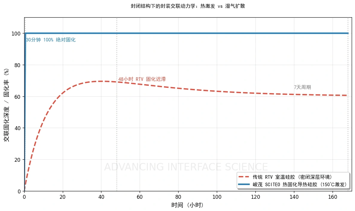
RTV crosslinking is triggered by water molecules in air. In the open, you get a tack-free skin in about 15 minutes, a cured bulk in 48 hours, and a fully developed network with stable mechanical and electrical properties in roughly 7 days. On an open board that rhythm is fine. Inside a sealed cavity it changes character.
The adhesive at the edge meets moisture first and skins over, forming a dense polymer barrier that cuts the diffusion path inward. Material deeper in the cavity never gets its reactant. Geometry compounds it: in a condensation system the cure rate depends on the moisture diffusion coefficient and the bond-line thickness, and cure depth scales roughly with the square root of time. Double the thickness and the core takes disproportionately longer to reach the same degree of cure. A cavity in the 10 mm class can sit at room temperature for weeks without ever reaching full conversion at the core. In deep-cavity potting and thick gasket molding, no process parameter buys that back. We have opened housings where the outer layer was already an elastomer and the core was still flowing. That is the root cause.
The Cost of Waiting Seven Days
Automotive and industrial lines watch work-in-process (WIP) velocity closely. A 48-hour to 7-day full-cure hold means temperature-and-humidity-controlled floor space stacked with semi-finished parts, which is a hard number to defend on a lean line. The more practical problem is that uncured material creeps and shifts during handling and stacking, and downstream alignment accuracy goes with it. The arithmetic is simple: schedule on a 7-day cure and the WIP buffer has to hold a week of output, tying up floor space and working capital at the same time.
Switching the Reaction Path
SCITEO's heat-cure system takes the addition-cure route: platinum-catalyzed hydrosilylation, where vinyl-terminated polysiloxane reacts with a Si-H crosslinker under a platinum complex to form the Si-CH2-CH2-Si network. Three consequences follow directly.
No byproducts. Addition cure releases no alcohol or oxime species, so the adhesive body does not trap voids left by volatilized byproducts, and a sealed cavity never develops a locally acidic or alcoholic atmosphere.
Low cure shrinkage. Condensation systems typically shrink 1%-3%; addition systems stay under 0.5%. Alignment stability in thin-wall sensors and precision optics depends on that difference.
No depth limit. Once conduction brings the whole part to temperature, the network forms throughout the adhesive at once, and cure depth is no longer tied to a diffusion length.
Handing Cure Control to Temperature
Once the driving force moves from ambient humidity to a controlled thermal field, the formulation work shifts with it.
Latent Catalyst vs. Working Life
At the bottom of the formulation sits a latent platinum catalyst paired with a temperature-threshold inhibitor. At room temperature, through refrigerated storage and the workshop window, the inhibitor occupies the platinum sites and the chains stay inert. Put the assembly in a tunnel oven or on a heated platen, reach roughly 120 °C, and the inhibitor leaves the platinum sites; crosslinking starts within minutes.
This is where the old contradiction of a one-component addition system sits. It has to survive and stay workable at room temperature, then cure fast and completely when heated. Inhibitor concentration and catalyst ratio set where the balance lands, and SCITEO pulls that point into the stencil-printing and precision-dispensing window through base-resin molecular-weight distribution control. Storage follows the same logic: keep it cold, let it return to room temperature before opening, and keep condensation off the surface.
Tack-Free Is Not Cured
Keep the two apart. A tack-free RTV surface says nothing about the interior, which can still be fluid. Degree of cure in a heat-cure system is quantified from residual reaction enthalpy by DSC, and first-article release should rest on residual enthalpy and a degree-of-cure profile rather than a thumb pressed into the surface. Hardness misleads, especially on parts with real thermal mass.
A 120-150 °C hold at 30 min takes the material from liquid to a crosslinked network, so parts cool and move straight into thermal-shock testing or assembly. Set against a 48-hour to 7-day room-temperature cycle, WIP inventory and flow time compress to their physical limit.
Match the Cure Window to Component Thermal Mass
Aluminum housings and thick baseplates carry real heat capacity. Ramp too slowly and the deep section sits in an under-temperature zone long enough to scatter the degree of cure. Ramp too fast and internal stress locks in before the filler network sets. The control variable should be the hold time a thermocouple measures after the component interior reaches 120 °C, not the oven setpoint. For mixed assemblies with very different thermal mass, a stepped ramp that equalizes the part before the hold segment removes most of the local over- and under-temperature trouble.
Where It Lands: Selected Demanding Service Environments
Material data only counts when it maps onto a real structure. These are among the application families putting the most pressure on sealed-structure thermal silicone today.
Humanoid Robot Joint Modules and Dexterous Hands
Embodied-AI and humanoid robots drive their axes with frameless torque motors, packing stator windings, reducers, encoders and driver boards into a very small joint volume. When heat cannot leave, winding temperature climbs, torque output sags, encoders and torque sensors drift, and whole-body motion accuracy follows.
Joint modules ask three things of a potting material. Copper-to-housing needs a continuous thermal path, and the 2.5 W/(m·K) network displaces the air sitting in those gaps. Stator and magnets need to be locked without adding stress, which is what a low-modulus, high-elongation network does: the load from frequent starts, stops and reversals lands on the adhesive rather than on the insulation system. And the joint lives in continuous vibration and drop impact, so the adhesive has to absorb that energy by deforming. Rigidity does not help here.
Industrial ECUs and Domain Controllers
Industrial controller (PLC) modules, smart-cockpit domain controllers and automotive ECUs are mostly aluminum housings around power devices. Heat travels through the thermal adhesive into the housing and out, while the CTE gap between aluminum, PCB and ceramic substrate accumulates into meaningful interfacial shear under wide-temperature service and thermal shock.
These assemblies rarely fail on cohesive strength. The interface is what eats service life: load cycles stack up, and the interface delaminates a little at a time. What SCITEO's heat-cure silicone brings to a macroscopic heterogeneous interface is distribution. The low-modulus elastic network converts concentrated destructive shear into elastic potential energy through chain stretching. On etched aluminum and anodized metal, 5 MPa lap-shear strength (per GB/T 7124) survives thermal-shock cycling with no delamination.
Automotive High Voltage: BMS, On-Board Chargers and Storage PCS
High-voltage electrical systems are where thermal conduction and insulation have to hold at the same time. Inside battery management systems (BMS), on-board chargers (OBC), traction inverters and energy-storage power conversion systems (PCS), bus voltage reaches the 800 V class, power devices switch continuously, and dielectric breakdown and electrochemical migration are both live risks.
Dielectric strength of 23 kV/mm (per GB/T 1408) together with volume resistivity of at least 1.5×10¹⁶ Ω·cm (per ASTM D257) keeps high-impedance isolation intact under damp heat and at a 220 °C service ceiling. Mobile-ion control at the formulation level addresses the slow path: electrochemical migration (ECM) and dendritic growth under humid bias. High-voltage cavities also need a flame-retardant backstop, and the elastomer body meets UL 94 V-0. Automotive qualification matrices for this class of part are usually built on ISO 16750-4 and AEC-Q100.
MV Isolation and Partial Discharge: Solid-State Transformers and DC Distribution
A solid-state transformer (SST) converts 10-13.8 kV medium-voltage AC to 800 V DC in a single stage, using silicon carbide devices to push switching frequency into the tens of kilohertz and shrink the high-frequency transformer. The architecture is moving into engineering programs for fast-charging sites, onboard rail power, microgrids and DC distribution. What holds up volume production is rarely the topology; it is the insulation system.
Partial discharge (PD) inside the high-frequency transformer's potting layer erodes the insulation system a little at a time, a failure path that engineering analyses record more often than power devices failing first. PD starts in small voids inside the insulation, and those voids often come from a CTE mismatch between the potting compound and the core or windings: thermal cycling pulls the interface open into micro-gaps where the field concentrates. Frequency and temperature are both climbing, and that only speeds the process up.
Temperature is the second thread. Losses in the high-frequency transformer and the MV power modules concentrate in windings and core, and heat can leave only through the potting layer toward the housing. Hot-spot temperature sets how much insulation life is left. Zoned potting is now established practice: potting the high-voltage coil assembly as a separate unit instead of casting compound and core together, specifically to avoid CTE-driven core cracking. The selection logic for power units and auxiliary electronics is the same: can the adhesive layer hold hot-spot temperature inside the insulation system's long-term working range, and will it pull the interface open under thermal cycling.
There are only three levers on the material side. First, lower the modulus so thermal cycling displacement is absorbed by the adhesive layer instead of the insulation interface. Second, keep the thermal network continuous so winding and core hot spots come down, because higher temperature pushes partial-discharge inception voltage (PDIV) lower; heat and insulation are a coupled problem at high voltage and high frequency. Third, control purity and mobile ions. On the DC side the field is unidirectional and persistent, so ion migration and dendrites are a more direct risk than on AC. Dielectric strength and volume resistivity hold the ground insulation, and a low-outgassing formulation keeps a sealed cavity free of condensation and deposition.
The quantitative gates have to line up too. Creepage distance and clearance are worked out against the insulation-coordination method of IEC 60664-1, housings and insulating parts commonly run a comparative tracking index (CTI) of at least 600 V, and PD-free designs target discharge below 5 pC. The potting step also has to drive down residual void density inside the adhesive layer. Voids are both where PD starts and a break in the thermal path, which is why vacuum deaeration and vacuum potting are not optional here.
On a fully cast high-frequency transformer, the main insulation is normally still carried by a cast epoxy system; a low-modulus silicone earns its place in power-unit, driver and auxiliary-electronics potting and in interface buffering. Insulation and safety verification for this equipment class can be framed around IEC 62477-2.
Fully Sealed Sensors and MEMS
Sensors want something different from a potting compound than power modules do, and the conflict sits elsewhere. The sensing structures in pressure sensors, accelerometers and gyroscopes are extremely sensitive to package stress. Raise the modulus and package stress travels into the sensing beam, bringing zero-point drift and sensitivity loss with it. A 56% elongation paired with a low-modulus network works as a stress buffer here, holding cure shrinkage and thermal expansion stress inside what the sensing element can take. The formulation also has to control low-molecular-weight siloxane volatiles and mobile ions so nothing condenses on the cold surfaces of a sealed cavity.
The Stress Ledger at a Macroscopic Interface
Die-level packaging is built around rigid matching: high-modulus, ultra-low-CTE epoxy against micron-scale thermal strain. At that scale the logic holds.
At board level or in system-level thermal design the ledger changes. Displacement grows from microns to millimeters, and the material no longer needs to resist movement. It needs to accommodate it.
Stress Equals Modulus Times Strain
Interfacial shear scales with that relation. Under thermal shock, aluminum moves a meaningful absolute distance; if the adhesive has high modulus and low elongation, that displacement becomes enormous interfacial shear, and either the adhesive fractures or the oxide layer on the substrate comes off with it.
The 56% elongation of SCITEO's heat-cure elastic thermal silicone corresponds to a very low modulus. As the aluminum moves, the adhesive absorbs the destructive strain energy by deforming, and both the structure and the substrate survive. High elongation plus 8.0 MPa tensile strength: toughness and strength are both required, and neither one alone is enough.
When Thermal Shock and Vibration Stack
On robot servo joints, heavy-duty automotive ECUs and outdoor base stations, thermal and mechanical loads arrive together. Tens of G of high-frequency vibration plus the occasional drop is a bad environment for a high-modulus adhesive: under a sudden peel load it cannot yield elastically, so it fractures brittlely, or it tears the metal surface before it lets go.
At 56% elongation the interface has enough compliant travel to absorb high-frequency impact energy, while 8.0 MPa tensile strength keeps the adhesive body from collapsing under extreme pull. Tensile properties are measured to ASTM D412, modulus and glass transition (Tg) to DMA, thermal cycling conditions are set from JEDEC JESD22-A104 or IEC 60068-2-14, and vibration-heavy programs are better served by putting all of them on one sheet. In combined thermal-vibration testing, higher-modulus samples tend to show interfacial whitening first; the low-modulus system that takes the displacement itself keeps a cleaner interface.
Heat and Insulation: Two Numbers That Mislead Alone
In an electromechanical assembly, a structural adhesive has three jobs at once: hold, conduct heat, insulate.
Interfacial Thermal Resistance Is Not Set by Conductivity Alone
In high-power devices such as high-current drone ESC modules, 5G-A base-station power amplifiers and photovoltaic inverter power stages, accumulated heat causes throttling or outright thermal failure. SCITEO's system packs micro- and nano-scale spherical alumina and boron nitride densely to form a continuous 2.5 W/(m·K) phonon path (per ASTM D5470).
Conductivity is only one term in thermal interface material (TIM) performance. Microscopic roughness between the heat source and the heat sink traps an air layer, and air conducts at roughly 0.024 W/(m·K). Leave that air in place and no filler network saves you. The adhesive displaces it under assembly pressure, converting point contact into areal contact, which is when the conduction capability actually shows up. It is also why the same product can measure out to noticeably different thermal resistance at different pressures and bond-line thicknesses.
Breakdown and Migration Are Different Problems
In high-voltage relay encapsulation, automotive BMS and MV-DC structures, breakdown resistance is a hard line. A dielectric strength of 23 kV/mm and volume resistivity of at least 1.5×10¹⁶ Ω·cm keep high-impedance isolation under long-term damp heat and at a 220 °C ceiling.
The other thread is easy to miss: mobile ions migrate along the field under humid bias and grow dendrites between closely spaced conductors. On DC there is no periodic field reversal, so migration accumulates in one direction and ion purity matters more. Mobile-ion control and crosslink-density design at the formulation level address that slow failure path.
Tear and Impact
A cured elastic network has to balance two failure modes: no fatigue-crack growth under high-frequency vibration, no brittle fracture under accidental impact. The 56% elongation and 8.0 MPa tensile combination, together with good substrate wetting and interfacial adhesion, is what carries structures such as large heat sinks bonded to dies and heavy-duty power modules.
Outgassing
Outgassing is the other invisible line in sealed potting. In vacuum or at elevated temperature, released volatiles condense on optical surfaces, sensing surfaces and probes; cleaning them is tedious, and on optics or space hardware the surface is usually written off. The industry quantifies the risk with total mass loss (TML) and collected volatile condensable materials (CVCM) per ASTM E595, and the conventional line is TML ≤1.0% and CVCM ≤0.10%. For optical surfaces and vacuum cavities, SCITEO pushes its low-outgassing grades further, to TML below 0.3% and CVCM below 0.02%. An addition-cure system does not depend on moisture diffusion and releases no alcohol byproduct, so the real variables become residual low-molecular-weight siloxanes and degree of cure, both closed out by high-purity raw materials plus adequate conversion control.
Can the Line Take It
A good material the line cannot run never reaches volume. Coating large thermal backplanes by single-dot dispensing is slow, and bond-line thickness (BLT) consistency is hard to hold.
SCITEO's one-component heat-cure system does not consume room-temperature working time, so the front-end process has room, and SMT stencil printing drops straight in.
Thixotropy and Shear Thinning
As the metal squeegee advances at a set pressure and speed, the adhesive forms a smooth rolling bead ahead of the blade. Viscosity collapses at high shear and the material fills the fine apertures; the moment the squeegee passes and shear is gone, viscosity recovers and the printed edge holds. Printable thermal interface materials are usually formulated in the tens of thousands to hundreds of thousands of mPa·s range, precision-dispense grades run up to the 6×10⁵ mPa·s class, and shear thinning plus thixotropic recovery have to line up with the print cycle for the deposit to stay consistent at speed.
Area Ratio and BLT
Release quality comes down to aperture area ratio and aperture-wall surface energy. Per the IPC-7525 stencil design guidelines, area ratio (aperture opening area to wall area) should be at least 0.66 and aspect ratio at least 1.5. Below that, adhesive clings to the walls, and what you see is skip printing and low deposit volume. SCITEO's work on base-resin molecular-weight distribution is aimed at widening the printing window, so one print lays down hundreds of thermal pads across an industrial backplane at micron-level thickness control. Confirm the moisture sensitivity level of the devices per IPC/JEDEC J-STD-020, then go straight to placement and oven cure.
One Material for Printing and Dispensing
The two processes are not mutually exclusive. Most lines combine them: precision dispensing for narrow gaps, blind holes and local reinforcement, stencil printing for large thermal pads and heat-spreading surfaces. Sharing one material across both requires viscosity and thixotropy that hold steady across different shear-rate regimes. Filler gradation and rheology additives are what make the material predictable in both the high-shear printing regime and the low-shear dispensing regime, which cuts the re-qualification work at changeover.
Selection Quick Reference
The table below compresses the mechanisms above into a checklist for design and process review:
| Application | Typical Failure Mode | Key Metrics | SCITEO Direction |
|---|---|---|---|
| Humanoid robot joint-module stator potting | Winding temperature rise, insulation aging, vibration abrasion | Thermal conductivity, elongation at break, low modulus, temperature rating | Heat-cure elastic thermal silicone |
| Industrial ECU and domain controller | Interfacial delamination, shear decay after thermal shock | Post-shock shear strength, CTE match | Heat-cure elastic thermal silicone |
| High-voltage BMS and storage PCS | Breakdown, electrochemical migration, damp-heat aging | Dielectric strength, volume resistivity, mobile ions | High-voltage insulating thermal potting system |
| Solid-state transformer and MV-DC power unit | Partial discharge in the potting layer, interface micro-gaps, hot spot | Low modulus with high elongation, dielectric strength, low outgassing | Heat-cure low-stress insulating potting system |
| Fully sealed sensor | Deep-section undercure, stress cracking, outgassing contamination | Full cure, low modulus, TML/CVCM | Heat-cure low-stress potting system |
| Large-area thermal backplane coating | Skip printing, stringing, uneven BLT | Thixotropy, area ratio, BLT consistency | Stencil-printable thermal silicone |
Closing
Choosing a cure mechanism is really choosing a degree of controllability. Room-temperature cure hands control to ambient humidity and structural geometry. Heat cure takes it back onto a temperature profile, and the deep-section problem inside a sealed structure goes away with it. SCITEO builds low modulus and high elongation into the formulation, so the interface absorbs macroscopic CTE mismatch, and keeps the thermal network continuous so hot spots come down. The material is compatible with stencil printing, so the line does not re-qualify at changeover. Working the material boundaries out at the design stage costs far less than chasing them in production.
This article is SCITEO Advanced Materials original technical content; unauthorized reproduction is prohibited.
Appendix: Process & Engineering Adhesive FAQ Index
Why does room-temperature-vulcanizing (RTV) silicone stay uncured deep inside a sealed cavity or a large metal sandwich?
Condensation-cure RTV crosslinks through moisture diffusion. In an open environment the edge skins over first and forms a dense polymer barrier that cuts the diffusion path inward, and cure depth scales roughly with the square root of time, so a thicker bond line needs disproportionately longer to reach the same degree of cure at the core. Once the potting volume is enclosed by a metal housing, the moisture supply itself is gone and the core can stay soft for weeks. Do not judge this by surface hardness. Open the part and look at the degree-of-cure profile, or measure residual reaction enthalpy by DSC.
How does the latent catalyst in a one-component heat-cure silicone trigger at 120 °C without reacting during cold storage?
The system runs platinum-catalyzed hydrosilylation, and the formulation carries an inhibitor that temporarily occupies the platinum active sites. At room temperature the inhibitor is stable and the chains do not react, which is what buys the working life and storage stability. Near 120 °C the inhibitor releases, the catalyst starts working, and crosslinking begins within minutes and runs to completion. The hard part is the balance point between working life and cure speed; SCITEO tunes inhibitor concentration, catalyst ratio and base-resin molecular-weight distribution together so that balance lands inside a window both stencil printing and precision dispensing can live with.
For stator potting in a humanoid robot joint module, why look at elongation and modulus instead of bond strength alone?
Joint modules rarely fail by static pull-off. They fail from winding temperature rise, high-frequency vibration and the stress cycling that comes with frequent starts and stops. Stress equals modulus times strain, so a high-modulus adhesive turns displacement into interfacial shear during thermal cycling and impact, and the load ends up on the insulation system and magnet positioning. A low-modulus, high-elongation network absorbs strain energy through its own deformation and drops the stress peak. Review thermal conductivity, elongation at break, modulus, temperature rating and post-shock shear retention as a set rather than ranking on one strength value.
How does a 2.5 W/(m·K) thermal silicone lower interfacial thermal resistance, and why displace the air layer first?
Interfacial thermal resistance has two terms: bulk resistance through the adhesive, and contact resistance at both interfaces. Microscopic roughness between the heat source and the heat sink always traps some air, and air conducts at about 0.024 W/(m·K), which makes it a very effective thermal insulator. The adhesive fills those micro-gaps under assembly pressure, converting point contact into areal contact, and only then does the 2.5 W/(m·K) filler network have a continuous phonon path to work with. When you verify to ASTM D5470, lock the pressure and bond-line thickness, because measured conductivity drifts with both.
In large-area stencil printing of thermal silicone, how do you reduce skip printing, stringing and uneven BLT?
Skip printing usually traces to one of two mismatches. Squeegee speed against the adhesive's shear-thinning rate: run too fast and the material has not liquefied in time to fill the apertures. Or insufficient area ratio at release, or excessive aperture-wall surface energy, which leaves adhesive clinging to the walls. Practically, hold squeegee speed at 15-30 mm/s, keep a uniform rolling bead 1-2 cm across ahead of the blade, clean the stencil underside with lint-free cloth on a schedule, and design to an area ratio of at least 0.66 per IPC-7525. SCITEO's work on base-resin molecular-weight distribution mainly widens the usable range of those parameters so the line is not running against the edge of the window.
For medium-voltage equipment such as solid-state transformers, what is the most overlooked potting risk?
Partial discharge (PD). PD in the high-frequency transformer potting layer erodes the insulation system a little at a time, and engineering analyses record that path more often than power devices failing first. PD starts in small voids inside the insulation, and those voids usually come from a CTE mismatch between the potting compound and the core or windings: thermal cycling pulls the interface open into micro-gaps where the field concentrates. The material response is to lower modulus so thermal displacement is absorbed by the adhesive layer rather than the insulation interface, and to keep the thermal network continuous so hot-spot temperature comes down and partial-discharge inception voltage (PDIV) climbs back. For this equipment class, insulation and safety verification can be framed around IEC 62477-2, creepage and clearance are worked out to IEC 60664-1, and PD-free designs target discharge below 5 pC.
Why does a platinum-catalyzed addition-cure silicone run into cure inhibition, and how does the line avoid it?
The platinum catalyst is sensitive to sulfur, amines and organotin compounds, and trace contamination can partially or completely prevent cure. Three common sources: amine residues carried in from flux left on pads, sulfur-bearing cleaning agents and sulfur-cured rubber gloves, and adjacent tin-catalyzed materials in the same area. The countermeasures are not complicated but have to be enforced: clean substrates with a deionized rinse, dedicate mixing and dispensing equipment, use a primer where needed, and keep tin-containing materials physically separated from addition-cure silicone on the line.
How do heat-cure silicone, thermal epoxy and thermal gel divide the work at selection?
Work backward from the failure mode rather than ranking on conductivity. Die-level bonding that needs rigid locking and low CTE is better served by thermal epoxy. Where interface tolerances are large, gaps are irregular and rework margin matters, thermal gel wins on low modulus and compressibility. Sealed-structure potting that has to move heat out without pushing stress into solder joints and insulation sits in between, and that is where a heat-cure elastic silicone lands: low modulus and high elongation make it more forgiving than epoxy through thermal cycling.