Connector & Harness Potting Compound Selection: Mil-Spec Thermal Shock, 800V High-Voltage and Medical Harness Sealing Physics
SCITEO epoxy potting system deconstructed: GJB 150 thermal shock crack resistance, low-surface-energy and primer interfacial anchoring, wicking suppression and helium leak-test release criteria
Executive Summary
A connector is the one node in an electrical link that absorbs electrical, thermal, mechanical and chemical stress at the same time. Once the potting layer gives way, the whole link slides toward insulation breakdown or intermittent contact. 800V platforms compress terminal spacing into the millimeter range, 224G backplanes squeeze the insertion-loss budget into fractions of a decibel, medical connectors must survive hundreds of autoclave cycles, and mil-spec circular connectors must hold hermeticity across a −55 °C to +150 °C swing. The applications differ, but the material review comes down to the same four quantities: rheological window, cure volume shrinkage, interfacial anchoring strength and thermo-mechanical stress absorption. Most connector potting disputes trace back to where those four pull against each other.
This article runs from material boundaries to application deployment. It opens with the rheological balance between penetration and anti-leak behavior and the mechanics of wicking suppression, moves to the crack-initiation model under GJB 150 thermal shock and the low-shrinkage rigid architecture that resists it, then covers interfacial anchoring for PA66, PBT, PPS, LCP and PTFE. The application sections map a selected set of interfaces: mil-spec circular connectors, 800V automotive high-voltage connectors, 224G backplanes with liquid-cooling quick disconnects, medical connectors and imaging harnesses, and energy-storage or robotic joint harnesses. Hermeticity release criteria close the loop. SCITEO delivers connector potting as a standalone product line, with one- and two-component epoxy systems, two interfacial process routes (plasma activation and primer), and the hermeticity validation sequence reviewed together at project kickoff.
Selection is not a contest of single-metric peaks. The rheological window, interfacial anchoring and thermo-mechanical stress absorption trade against each other, and whether one formulation can hold margin across all three decides whether the compound survives on a production line.
Core Parameter Comparison
The table compares SCITEO connector potting epoxies against conventional potting compounds:
| Parameter | SCITEO | Industry Baseline | Test Standard |
|---|---|---|---|
| Thermal shock range | −55 °C to +150 °C | −40 °C to +125 °C | GJB 150.5A |
| Thermal cycles | ≥1000 | 200-500 | GJB 150.5A |
| Volume resistivity | >10¹⁴ Ω·cm | 10¹²-10¹³ Ω·cm | GB/T 31838.2 |
| Cure volume shrinkage | <0.06% (low-shrinkage grade) | 0.5-2% | ISO 2577 |
| Post-cure hardness | Shore D 80+ | Shore D 60-80 | ASTM D2240 |
| Copper-plated shear strength | 26 MPa | 8-15 MPa | GB/T 7124 |
| Shear retention after thermal shock | 92% (TC500) / 90% (TC1000) | <70% | GJB 150.5A / GB/T 7124 |
| Shear retention after 85/85 | 76% (1000 h) | <50% | JESD22-A101 |
| Interfacial failure mode | Cohesive (after 1000 cycles) | Interfacial peel | Tear test |
| Substrate coverage | PA66/PBT/PPS/LCP/PTFE | General plastics | Not applicable |
Whether those numbers hold at the same time depends on whether four things couple properly: the pseudoplastic structure decides whether the gap fills without overflowing, the latent cure system decides how much margin remains in cure shrinkage and residual stress, the coupling layer and surface activation decide whether interfacial anchoring beats the compound's own strength, and the ion and moisture levels decide insulation margin under damp heat. The hard part is holding margin across all four inside one formulation, not pushing any single metric up.
Connector Sealing Boundaries: From Millimeter Cavities to Sub-Millimeter Gaps
Macro-scale electrical connectors differ from wafer-level semiconductor packaging in where the stress originates and how failure propagates. Connectors deal with assembly gaps, stranded wire, dissimilar platings and repeated mating cycles; wafer-level packaging deals with sub-micron alignment and cleanliness. A connector seal is really three interfaces: the annular gap between pin and housing, the capillary channel between stranded copper and insulation jacket, and the mating face between housing and panel or PCB. Each has its own material stack, tolerance and load case, and a single potting step has to cover all three.
Three Sealing Routes and Their Division of Labor
Automotive harness is the most heavily automated sealing environment, and the process has split into three routes. Single Wire Seal (SWS) forms a circumferential closure at each wire entry with a molded grommet or dispensed sealant, targeting the single-point leak between wire and housing. Formed-In-Place Gasket (FIPG) dispenses a sealing bead onto the mating face, absorbing housing flatness variation in the ±0.1 to 0.2 mm band and tolerating larger gaps through higher compression. Potting fills the entire backshell cavity and carries sealing, retention, insulation and thermal conduction at once.
High-end connectors usually stack all three. The crimp zone and the stranded-wire root are the primary moisture paths, external grommets cannot reach them, and potting is the only step that closes the path as a whole. Conformal coating is often presented as a lighter substitute for potting, but it only films the surface: the pin annulus, the inter-strand channel and the crimp zone stay open, and moisture bypasses the coating from the termination side. Where long-term hermeticity is required, coating is at best a supplement. SCITEO's delivery basis on this step is to ship penetration depth, wick height and interfacial anchoring as three data sets, not just the viscosity and hardness of a compound.
The Rheological Balance Between Penetration and Anti-Leak
One formulation has to satisfy two opposing rheological requirements. In the fill stage the compound needs a low enough initial viscosity to travel by capillary action into micro-gaps between pin and housing and displace air; trapped air otherwise becomes a partial-discharge channel under high voltage and a hydrolysis initiation site under damp heat. In the static stage it needs a high enough yield stress to stop flowing out through bottom pin holes, the failure the line calls leakage.
SCITEO builds a pseudoplastic structure into the epoxy: viscosity drops quickly as shear rate rises to complete wetting and leveling, the thixotropic structure recovers within seconds once shear is removed, and yield stress holds at rest to seal the gap. The measurable criteria are thixotropic index and recovery time, which together set dot geometry consistency and cavity fill integrity. The common misjudgment is checking a single viscosity number while ignoring the recovery curve, which shows up as a batch that does not leak early in a continuous dispense run and starts leaking later.
Wicking and Harness Embrittlement
The most concealed failure in harness potting is wicking. Epoxy climbs the inter-strand gaps of stranded copper by capillary action, and once cured the harness goes from flexible to rigid: any bend below the minimum radius fractures at the potting boundary and transfers stress straight into the crimp zone, producing broken strands or contact-resistance drift. Detection is expensive because appearance and electrical test are usually clean at the factory.
Suppression works from two sides. On the material side, room-temperature yield stress and thixotropic recovery are tuned to close the inter-strand channel, and the filler particle-size ceiling is capped so coarse particles cannot prop the channel open. On the process side, dispense volume, dispense position and staged cure are controlled so the compound gels before it reaches the target height. SCITEO supplies viscosity grade and dispense-path matching, and wick height is written into the data package as a delivery acceptance item.
Extreme-Environment Endurance: GJB 150 Thermal Shock and Rigid Crack Resistance
The Crack-Initiation Model Under Mil-Spec Thermal Shock
Military and high-grade automotive connectors must pass extreme thermodynamic qualification. The temperature shock test in GJB 150, Environmental Test Methods for Military Equipment, and its MIL-STD-810 counterpart drive samples between −55 °C and +125 °C, with some programs tightened to +150 °C, in rapid transitions. Cycle counts typically start above 500, and volume release commonly requires 1000.
The failure chain breaks into four steps. Metal pins sit near 17 ppm/°C, engineering-plastic housings in the 20 to 50 ppm/°C band, and epoxy compounds in the 30 to 60 ppm/°C band; the differences convert into interfacial shear stress during the rapid cooling segment. Once stress exceeds interfacial anchoring strength, micro-cracks initiate, propagate along the filler-to-matrix interface, and end as macroscopic cracking or delamination from the housing, after which moisture and salt spray enter through the gap and drive leakage current up. The empirical rule from screening work is that most interfacial problems surface in the cold segment rather than the hot one, which is why low-temperature embrittlement has to be qualified separately.
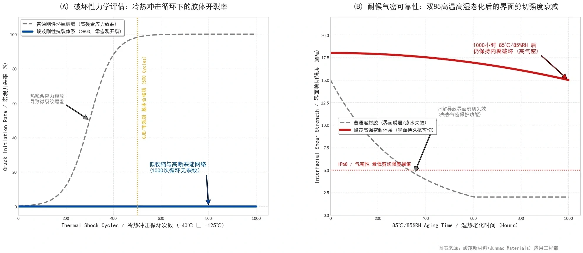
SCITEO's screening record over 1000 cycles is 90% shear retention with the fracture path still inside the compound.
Low-Shrinkage Cure Chemistry and a High-Fracture-Energy Network
Connector potting sets post-cure hardness above Shore D 80 (tested to ASTM D2240) to resist disassembly, mechanical damage and to hold high insulation. The claim that high hardness forces high brittleness holds only when cure shrinkage is uncontrolled. The root cause of cracking in ordinary rigid epoxies is an exotherm peak that is too high and volume shrinkage that is too large, leaving residual internal stress close to the material's critical fracture energy after cooldown.
SCITEO treats exotherm and volume shrinkage as one coupled set of variables. A latent cure system flattens the crosslinking exotherm and holds cure volume shrinkage within 0.5%, with low-shrinkage grades below 0.06% (tested to ISO 2577), removing residual stress at the source. On the fracture-mechanics side, a rigid densified network is built into the resin matrix and filled with graded, surface-treated silica micro-powder, so the filler-to-matrix bond is strong enough to arrest and deflect micro-crack tips. The result is a Shore D 80+ body at the macro scale that still carries large-area crack deflection and bridging energy dissipation at the micro scale.
Salt Spray, Fluids and Damp Heat
Connectors in service also face neutral salt spray, engine oil, coolant, fuel and cleaning agents. The standard basis is neutral salt spray at 5% NaCl and 35 °C (ISO 9227 / GB/T 10125), where cadmium-plated mil-spec shells commonly require 500 hours and stainless or titanium shells more. Damp heat runs at 85 °C/85% RH (JEDEC JESD22-A101 or GJB 150.9), and automotive programs add the mechanical load conditions of ISO 16750-3.
The material-side thresholds are water absorption and ionic content. Lower water absorption means less volumetric swelling and less dielectric-constant drift under damp heat, and less vapor source for the popcorn effect. Lower mobile ion content (Na⁺, K⁺, Cl⁻) means fewer charge carriers for electrochemical migration under humidity and bias. SCITEO delivers water absorption, mobile ion content and post-salt-spray shear retention together, so the damp-heat and corrosion margin can be calculated rather than assumed.
Interfacial Anchoring: From PA66/PBT/LCP to PTFE
Low Surface Energy and Mold-Release Contamination
Connector housings are dominated by glass-filled PA66, PBT, PPS and LCP. These materials combine low surface energy with high crystallinity, and injection molding adds mold-release agents, so the interface starts out hard to wet. Plasma treatment gives a quantitative reference: untreated PBT measures roughly 30 mN/m, and treated PBT rises above 72 mN/m. Only past that threshold can the compound wet completely and form a continuous interface without voids.
LCP is a special case. Its in-plane CTE is only 2 to 10 ppm/°C, far from copper alloy at 17 ppm/°C, so interfacial shear stress concentrates more sharply under thermal cycling. At the same time it holds a dielectric constant of 2.5 to 3.2 at 20 GHz, which makes it the housing material of choice for 224G backplanes. High-speed connector seals therefore carry high-frequency electrical requirements and high interfacial stress at the same time, and the compound has to deliver low dielectric loss and low-modulus stress buffering together.
Tracking resistance on the housing is a further constraint. High-voltage connectors generally specify high-CTI engineering thermoplastics, with CTI measured to IEC 60112, while the compound raises its tracking resistance through an inorganic filler system. Creepage distance, clearance and tracking performance then form one coordinated insulation scheme. SCITEO brings the compound's own CTI value into that review alongside the housing material, so a scheme is not signed off on the housing figure alone.
Plasma Activation and Coupling-Layer Design
Interfacial anchoring breaks into three sequential steps. The first is surface activation: plasma treatment cleans both metal pins and plastic housing, removes mold-release and machining oils, and generates hydroxyl and carboxyl groups on the surface. The second is coupling-layer design: macromolecular coupling groups and tackifying resin are grafted into the epoxy so that, during cure, they bond chemically with the trace polar groups on the plastic surface and with the oxide layer on the plated metal, forming molecular-level anchoring. The third is cure-profile matching: a stepped ramp lets the compound reach full interfacial wetting before gelation, so early crosslinking cannot lock the wetting path shut.
The order of these three steps is not interchangeable. A frequent line problem is a low-temperature pre-cure that sets the compound shape before a high-temperature crosslink, apparently shortening takt but in practice removing flow before the interface is wetted, which lands adhesion data well below laboratory values. For housings with complex geometry where plasma cannot reach shadowed areas, a primer is the parallel route: it carries the active groups into the gap in solution first, and the compound's own coupling system completes the grafting. SCITEO publishes window parameters for both routes and writes post-activation hold time and dyne-level acceptance into the process document.
Failure-Mode Readout: Cohesive Failure Versus Interfacial Peel
The most effective way to verify interfacial margin is a destructive tear test that records both force and fracture location. After 1000 thermal cycles, if the fracture surface sits inside the compound, the mode is cohesive failure, which means interfacial adhesion already exceeds the compound's own strength and the seal has margin. If the fracture surface follows the housing interface, the mode is interfacial failure, and the problem usually sits in surface preparation and the coupling layer rather than in compound strength. A strength number alone cannot separate these two modes, yet they point to completely different corrective actions.
SCITEO's release criterion here is explicit: after aging, the copper-plated and engineering-plastic interface must fail cohesively, and fracture location is recorded so engineers can judge remaining margin. The wide-temperature rigid grade measures 26 MPa shear on copper plating with no edge chipping across −55 °C to 280 °C, retains 92% shear after 500 GJB 150 thermal shock cycles, and retains 76% after 1000 hours at 85 °C/85% RH.
Material Logic for Selected Applications
Military Circular Connectors and MIL-DTL-38999
Military circular connectors are dominated by GJB 599 (intermateable with MIL-DTL-38999) and GJB 598 (corresponding to MIL-C-26482). Shells are typically aluminum alloy or stainless steel, contacts are gold-plated, and sealing is provided at both the mating face and the backshell. Operating range runs −65 °C to +200 °C, mating life is 500 cycles, random vibration covers 10 to 2000 Hz, and shock reaches 300 g for 3 ms. High-density insert arrangements pack 128 contacts into one shell with power, coaxial, twinax and optical contacts mixed. Insulation resistance is specified in the 3000 to 5000 MΩ band at ambient and above 100 MΩ after damp heat.
Backshell potting for these parts has to satisfy three conditions at once: no cracking at −55 °C, insulation resistance still above 100 MΩ after 500 hours of neutral salt spray and 28 days of damp heat, and no termination-zone displacement from compound creep after mating cycles and vibration. The copper-plating and PTFE combination is the classic problem on this interface. PTFE has extremely low surface energy and strong chemical inertness, forms essentially no chemical bond with conventional adhesives at room temperature, and a marginal wrap delaminates instantly at low temperature, leaving a gap at the wire root. SCITEO delivers a PTFE-specific surface activation process together with a dedicated coupling system, holding interfacial continuity through the cold segment while suppressing wicking on stranded wire.
800V Automotive High-Voltage Connectors and Charging Inlets
Automotive harness carries more sealing interfaces than any other platform, with 1500 to 3000 connectors per premium vehicle, each one a potential moisture and salt-spray entry point. Higher voltage raises the bar sharply: on an 800V platform, even trace moisture between terminals can initiate arcing, and safety functions such as the high-voltage interlock loop (HVIL) and connector position assurance (CPA) require the seal to preserve first-mate/last-break sequencing and latch verification through repeated mating cycles. The governing automotive test specifications are LV 214 and USCAR-2, charging inlets are qualified separately to IEC 62196, environmental testing follows ISO 16750-3, sealing must reach IP67 and often IP6K9K with IPX8, housings are typically PBT, PPS or glass-filled PA66, and upper operating temperature sits near 150 °C.
Three technical barriers dominate high-voltage potting. Creepage distance and clearance must both hold: terminals need millimeter-scale creepage path, and the compound must be a low-ion insulating body, because any air gap or ionic contamination shortens the effective creepage path and can trigger partial discharge or arcing under trace moisture, which makes partial-discharge inception voltage an admission criterion for high-voltage potting. Potting must be void-free: vacuum degassing and staged dispense are standard practice, since voids weaken insulation and sealing together. And thermal-mismatch stress must be absorbed, because the CTE gap between copper alloy terminals and PBT housings accumulates interfacial displacement over thermal cycling and eventually drives peel. SCITEO covers insulation, sealing and stress buffering with a low-shrinkage, low-absorption, low-modulus epoxy system, and reports partial-discharge inception voltage and non-destructive void inspection alongside shear retention after −40 °C to +125 °C cycling as delivery metrics.
224G Backplanes, Liquid-Cooling Quick Disconnects and AI Data Center Harness
AI data centers have moved the connector role from conduction to signal-integrity constraint. 224G per lane is in volume deployment and 448G pre-production samples are moving in parallel, and the OIF CEI-448G framework has put 448G channel definitions, modulation schemes and test basis on the table. At 448G, staying on PAM4 would double the symbol rate to 112 GBd while usable bandwidth in today's copper connector links stalls in the 90 GHz class, so the channel budget runs out before device specifications do, which is why the framework lists higher-order modulation such as PAM6/PAM8 as a break-out direction. Attenuation, crosstalk, reflection and jitter then consume the budget quickly, pushing copper interconnect toward co-packaged copper and near-package copper architectures that place the connection as close as possible to the switch ASIC and compute die, while longer spans go to co-packaged optics (CPO) and near-package optics (NPO). The cost of that route can be measured directly: a 448G co-packaged copper prototype channel lands near 20 dB insertion loss above 100 GHz. This puts two new requirements on the potting compound: dielectric performance and cure displacement.
Dielectric performance means the compound must hold low dielectric constant and low loss tangent above 90 GHz; any ionic contamination or moisture uptake raises dielectric loss, which converts into insertion loss and eye-diagram margin. Cure displacement means shrinkage must be low enough to preserve micron-scale alignment tolerance in near-package interconnect, where it directly shifts the coupling position and breaks impedance continuity.
Liquid cooling has added a new connector category: universal quick disconnects (UQD/UQDB series). Under the Open Compute Project (OCP) UQD Specification Rev 1.0, couplings are rated to roughly 100 psi maximum working pressure and 300 psi minimum burst pressure, must disconnect drip-free while pressurized, limit fluid loss per disconnect to the 0.02 to 0.07 mL band, survive 5000 mating cycles, and remain compatible with deionized water and glycol coolants. Liquid cooling is also moving inside the module: pluggable optical modules now carry the cold plate in the module body and connect to the liquid manifold through miniature quick disconnects, removing the dry-contact thermal interface between module and external cold plate. Housing seals and tail-wire potting on these parts face pressure cycling, coolant swelling and a 45 °C warm-water duty cycle at the same time, so the compound must be validated on post-immersion strength retention and volumetric change. SCITEO delivers media compatibility and pressure-cycle data as a pair for this interface.
Medical Connectors and Imaging Harnesses
Medical connectors draw their sealing requirements from a different constraint: sterilization and biocompatibility. Reusable instruments must survive hundreds of autoclave cycles; single-use devices are typically sterilized with ethylene oxide (in the spirit of ISO 11135) or gamma irradiation (ISO 11137, commonly in the 25 kGy band). Biological evaluation on the material side sits under the ISO 10993 series, and medical electrical equipment safety follows the patient and operator protection requirements of IEC 60601-1. Endoscopes, patient-monitoring leads, surgical robot cables and imaging-system high-voltage harnesses are the representative interfaces.
Selection logic here differs from the previous two classes. Repeated autoclave cycles mean the compound must withstand high-temperature saturated steam and the condensate attack of the depressurization phase; a system with insufficient crosslink density shows surface hydrolysis and volumetric swelling after a few dozen cycles, followed by seal failure. Gamma irradiation drives chain scission and crosslinking at the same time, so shear strength and insulation performance must be re-confirmed after irradiation rather than inherited from pre-irradiation data. Sterilant residue and extractables feed directly into the biocompatibility conclusion, which makes mobile ion content and outgassing data mandatory material-side deliverables. SCITEO supplies low-ion, low-outgassing, radiation-tolerant epoxy systems for these interfaces, with pre- and post-sterilization shear retention and insulation resistance shipped in the data package.
Energy Storage, Photovoltaic and Robotic Joint Harnesses
Electrochemical energy storage and photovoltaics push connectors into long-term outdoor duty. DC-side voltage has entered the 1500V class, so connectors must satisfy IP68 together with long-term UV aging, and volumetric change rate plus interfacial retention under outdoor temperature and humidity cycling become primary metrics; coolant leakage and condensation duty add a further insulation margin check. Robotic harness brings a different constraint to the front. Humanoid and embodied-AI joint modules stack motors, encoders and reducers into tens of millimeters, and the harness must hold conduction through hundreds of thousands of bend cycles plus continuous vibration. Beyond vibration damping and sealing, the potting compound has to stay low-modulus and bend-tolerant, so it does not turn a flexible harness into a brittle one. SCITEO delivers low modulus, bend tolerance and low water absorption as a triple, with conduction-resistance drift after bending included in validation.
Hermeticity Validation: From IP Rating to Helium Fine Leak
IP Ratings and the Pressure-Decay Method
Whether potting actually works is settled by hermeticity validation, and the conventional basis runs at two levels. Ingress protection follows IEC 60529: IP67 corresponds to 1 m of water for 30 minutes with no ingress, and IP68 to deeper pressure and longer immersion. Ratings that carry a K belong to the ISO 20653 road-vehicle system: IP6K9K is judged under 80 to 100 bar hot water at 80 °C sprayed at close range, a far higher mechanical load than the static head behind IPX7, and a pass at IP6K9K does not cover the IP67 immersion requirement. Quantitative measurement follows the immersion-under-pressure method of IEC 60512-14-4 together with the pressure-decay method of USCAR-2, pressurizing in the 10 to 50 kPa band and measuring leak rate, where the automotive release threshold typically lands between 0.5 and 1 cc/min. Temperature stabilization must complete before measurement, because pressure drift from thermal gradients is misread as leakage, and that is where most scattered hermeticity data comes from.
An IP rating and a helium leak rate are frequently conflated, but they are not equivalent. An IP rating describes dust and water protection under defined conditions, while helium mass spectrometry reports a gas leakage rate. The two are complementary, not interchangeable, and reading a helium result as an IP rating is the most frequently made error in hermeticity acceptance.
Helium Fine Leak and Glass-to-Metal Seals
Where hermeticity requirements tighten further, pressure decay no longer has the resolution, and tracer-gas testing to ISO 20485 governs. Glass-to-metal sealed military and space connectors are normally judged to MIL-STD-883 Method 1014, where the glass-to-metal interface can reach the 10⁻⁷ atm·cc/s class; when the design target tightens to the 10⁻⁹ atm·cc/s class, ceramic-to-metal sealing carries more margin than glass sealing. Polymeric potting systems are not glass seals, but they still have to produce reproducible data under helium or pressure decay. SCITEO matches the method to the customer's acceptance basis and issues the report, while recording test temperature, cavity volume and stabilization time so that the same material cannot produce mutually incompatible conclusions in different laboratories.
Thermal Shock First, Hermeticity Second
Verification sequence is more easily overlooked than verification method. A hermeticity pass in the as-built state does not demonstrate reliability; the real risk appears after reflow, thermal shock and 85/85 aging, when the interface has already absorbed thermo-mechanical stress and hydrolysis. Testing hermeticity at that point is what exposes cumulative damage. SCITEO builds the qualification sequence as pre-treatment, aging, hermeticity, placing reflow preconditioning (J-STD-020), thermal shock and damp-heat aging ahead of the hermeticity decision and running the same lot through the sequence.
The sequence also carries diagnostic value. If hermeticity fails only after aging, the cause points to interfacial anchoring and cure shrinkage; if it fails before aging, the cause usually sits in dispense volume, vacuum degassing or cavity design. The two classes require completely different corrective action, so sequence directly determines how fast a problem can be localized.
Connector Potting Compound Selection Quick Reference
At review stage, this table can be used directly as the basis for comparison:
| Interface | Typical Failure Mode | Key Criteria | SCITEO Direction |
|---|---|---|---|
| Military circular connectors and backshell potting | Cold cracking, interfacial peel, insulation drop after salt spray | GJB 150 thermal shock, 500 h salt spray, cohesive failure | Mil-spec connector potting epoxy (wide-temperature rigid grade) |
| 800V automotive high-voltage connectors and inlets | Creepage failure, void discharge, terminal peel | Low ion content, void-free, PD inception voltage, LV 214 / USCAR-2 | High-voltage insulation potting epoxy (low-shrinkage low-absorption grade) |
| 224G backplanes and near-package interconnect | Rising dielectric loss, cure displacement breaking impedance | Low dielectric constant, low loss tangent, low cure shrinkage | High-speed connector potting epoxy (low-shrinkage low-dielectric grade) |
| Liquid-cooling quick disconnects and coolant lines | Coolant swelling, seal failure under pressure cycling | Media compatibility, shear retention after pressure cycling | Coolant-resistant sealing epoxy (media-resistant grade) |
| Medical connectors and imaging harnesses | Autoclave hydrolysis, post-irradiation strength decay | ISO 10993, IEC 60601-1, post-irradiation retention | Medical clean epoxy (sterilization- and radiation-tolerant grade) |
| Energy storage and photovoltaic connectors | UV aging, interfacial failure after damp heat | IP68, UV aging, volumetric change rate | Outdoor weatherable potting epoxy (low-absorption grade) |
| Robotic joints and flexible harness | Bend fracture, compound embrittling the harness | Low modulus, bend tolerance, conduction-resistance drift | Low-modulus flexible potting epoxy (bend-tolerant grade) |
Conclusion
Connector potting reviews tend to stall at the same point: the parameter table is complete, but nobody can say how much margin is left. Interfacial margin after 1000 cycles, the hermeticity delta before and after aging, the relationship between wick height and minimum bend radius. Most of those numbers are never recorded at prototype stage, so the problem waits for system vibration test or a field return to surface.
On this product line, SCITEO ships more than a compound. The thermo-mechanical boundary from −55 °C to +150 °C, the rheological boundary set by yield stress and thixotropic recovery, the interfacial boundary set by plasma activation and the coupling layer, and the cleanliness boundary set by mobile ions and water absorption all ship with the material. A process engineer who has those four boundaries can recalculate margin on their own line instead of resting the conclusion on a supplier's sample performance.
This article is SCITEO Advanced Materials original technical content; unauthorized reproduction is prohibited.
Appendix: Process & Engineering Adhesive FAQ Index
When connector potting cracks after thermal shock, is the root cause compound strength or interfacial stress?
In most cases the root cause is interfacial stress rather than bulk compound strength. Metal pins sit near 17 ppm/°C, PA66 and PBT housings fall in the 20 to 50 ppm/°C band, and epoxy compounds fall in the 30 to 60 ppm/°C band. Those differences convert into interfacial shear stress during the rapid cooling segment, and once interfacial anchoring strength cannot absorb the displacement, cracks initiate at the interface and propagate along the filler-to-matrix boundary. The diagnostic is a tear test after aging that records fracture location as well as force: a fracture inside the compound is cohesive failure and means the interface still has margin, while a fracture along the housing interface points to surface preparation and the coupling layer. SCITEO holds cure volume shrinkage within 0.5%, and below 0.06% on low-shrinkage grades, to remove residual stress at the source, and raises interfacial anchoring strength with a coupling layer at the same time.
Why do potting compounds leak, and why do they wick up a harness?
Both symptoms come from opposite sides of the same set of rheological parameters. Leakage happens in the static stage: insufficient yield stress lets the compound flow out through bottom pin holes, and once cured it contaminates the contact surfaces and causes intermittent contact. Wicking, formally capillary wicking, happens in the inter-strand gaps of stranded copper: capillary action carries compound up the conductor, and after cure the harness turns from flexible to rigid, fractures at the potting boundary on bending and transfers stress into the crimp zone. SCITEO puts both symptoms on one set of rheological parameters: a pseudoplastic structure holds yield stress at rest to seal the gap, thixotropic recovery is tuned into the seconds range so the compound gels before reaching target height, and wick height becomes a delivery acceptance item.
PA66, PBT and LCP have low surface energy and carry mold release. How is long-term adhesion guaranteed?
With interface chemistry and process control working together. On the material side, macromolecular coupling groups and tackifying resin are grafted into the epoxy so that, during cure, they bond chemically with trace polar groups on the plastic surface and with the oxide layer on the plated metal. On the process side, plasma activation comes first: untreated PBT measures roughly 30 mN/m, and activation lifts it above 72 mN/m, which is the threshold where the compound can wet completely and form a continuous interface while also removing mold release and machining oils. For housings with complex geometry where plasma cannot reach shadowed areas, a primer is the alternative route, carrying the active groups into the gap in solution. LCP deserves separate attention, because its in-plane CTE is only 2 to 10 ppm/°C, far from copper alloy, so interfacial shear stress concentrates more sharply and the compound also needs low-modulus stress buffering.
PTFE wire jackets barely bond to anything. How do military connectors seal that interface?
PTFE has extremely low surface energy and strong chemical inertness and forms essentially no chemical bond with conventional adhesives at room temperature, so a marginal wrap delaminates instantly at low temperature and leaves a gap at the wire root. The workable route pairs a PTFE-specific surface activation process with a matching coupling system, upgrading the interface from physical encapsulation to chemical anchoring, then qualifying it at −55 °C. SCITEO ships this interface as a process package, with activation window, hold time and interfacial continuity after low-temperature cycling written into the process document, so customers do not have to search for parameters on the production line.
Why can a rigid potting compound above Shore D 80 still resist cracking?
High hardness does not force high brittleness, provided cure shrinkage and residual internal stress stay controlled. Connector potting requires above Shore D 80 (tested to ASTM D2240) to resist disassembly and mechanical damage, and ordinary rigid epoxies crack because the crosslinking exotherm runs too high and volume shrinkage runs too large, leaving residual stress close to the critical fracture energy after cooldown. SCITEO flattens the exotherm with a latent cure system and holds cure volume shrinkage within 0.5%, then builds a rigid densified network into the resin matrix and fills it with graded, surface-treated silica micro-filler so crack tips are arrested and deflected at the micro scale. Macro-scale rigidity and micro-scale energy dissipation have to hold at the same time for rigid crack resistance to have a physical basis.
How should connector hermeticity be verified, and why test it only after thermal shock?
A hermeticity pass on an as-built part does not demonstrate reliability. The real risk appears after reflow, thermal shock and 85/85 aging, when the interface has already absorbed thermo-mechanical stress and hydrolysis, and testing hermeticity at that point is what exposes cumulative damage. Quantitative measurement uses the immersion-under-pressure method of IEC 60512-14-4 together with the pressure-decay method of USCAR-2, pressurizing in the 10 to 50 kPa band and measuring leak rate, where automotive release thresholds typically land between 0.5 and 1 cc/min. Ingress protection follows IEC 60529 for IP67 and IP68, with IP67 at 1 m of water for 30 minutes. Ratings that carry a K belong to the road-vehicle system: IP6K9K is judged to ISO 20653 under 80 to 100 bar hot water at 80 °C sprayed at close range, which is a different basis from IP68 immersion, and the two data sets cannot substitute for each other. An IP rating and a helium leak rate are not equivalent: the first describes dust and water protection under defined conditions, the second reports a gas leakage rate. Tracer-gas fine leak testing on resin-potted parts follows ISO 20485, while glass-to-metal sealed military and space connectors are judged to MIL-STD-883 Method 1014, reaching the 10⁻⁷ atm·cc/s class; tightening the target to the 10⁻⁹ atm·cc/s class favors ceramic-to-metal sealing. Temperature stabilization must complete before any measurement, or pressure drift from thermal gradients is misread as leakage.
What extra requirements do 800V automotive high-voltage connectors and 224G backplanes place on potting compound?
They target different physical quantities. The 800V side is about insulation and creepage: terminals need millimeter-scale creepage path, and the compound must be low-ion and void-free, because air gaps and ionic contamination shorten the effective creepage path and can trigger partial discharge or arcing under trace moisture, which is why partial-discharge inception voltage is treated as an admission criterion. The 224G side is about dielectric behavior and displacement: at 448G, staying on PAM4 would double the symbol rate to 112 GBd while usable bandwidth in today's copper connector links stalls in the 90 GHz class, so the OIF CEI-448G framework lists higher-order modulation such as PAM6/PAM8 as a break-out direction; the compound still has to hold low dielectric constant and low loss tangent across that band, since moisture uptake and ionic contamination raise dielectric loss and convert into insertion loss and eye-diagram margin. Co-packaged and near-package copper architectures compress alignment tolerance into microns, where cure shrinkage directly shifts the coupling position. SCITEO answers both classes with a low-ion insulating system and a low-shrinkage low-dielectric system respectively, and includes post-cycling insulation resistance and insertion-loss drift in validation.