How to Choose a UV-Cure Adhesive: Alignment Shift, Black Deep Cure and UV-Thermal Dual Cure
SCITEO draws the selection boundaries of UV-cure adhesives from automotive camera modules, LiDAR and XR waveguides, across three physical constraints: alignment shift, deep cure and shadow-zone crosslinking
Abstract
Optical module assembly moved into the sub-micron range long ago, and the structural tolerance left for a bond line often adds up to a few tens of microns. Seconds-fast, on-demand cure put UV adhesives at the center of automotive camera, LiDAR, XR waveguide and co-packaged optics lines. The hardest step in selection happens at the instant of cure, when several physical and chemical transformations run inside the bond line at once: volume shrinkage pulling the optical axis off position, interfacial stress building as the polymerization exotherm and modulus rise together, a cure gradient created where shielding filler consumes photons, and shadow zones where geometry keeps photons out entirely. Miss any one of those four and speed stops converting into yield.
SCITEO Advanced Materials organizes its optoelectronic packaging interface platforms around those same four boundaries. What follows breaks shift magnitude, depth of cure and retention down item by item, with numbers a process engineer can check at design review against ISO 2577, GB/T 7124, ASTM E595 and JEDEC JESD22-A101.
Core Parameter Comparison
The table below puts SCITEO light-cure and UV-thermal dual-cure platforms in the same coordinate system as industry-typical UV adhesives. The left column is where SCITEO stands, the middle column is what the same price band usually delivers, and the right column is how each figure is judged.
| Parameter | SCITEO | Industry Typical | Test Standard |
|---|---|---|---|
| Cure volume shrinkage | <0.6% | 3-5% | ISO 2577 |
| Deep cure in black light-shielding adhesive | 1.5-2.0 mm | <0.1 mm (surface cured, interior liquid) | LED irradiation dose verification |
| Photoinitiator absorption wavelength | 395-405 nm (red-shifted) | 365 nm | UV-Vis absorption spectroscopy |
| UV fixture time | 2-3 s | 10-30 s | LED irradiation dose verification |
| Dual-cure shear strength | ≥20 MPa | 10-15 MPa (single UV) | GB/T 7124 |
| Degree of cure in shadow zones | >95% (latent epoxy ring-opening) | Liquid residue | DSC residual reaction enthalpy |
| Pull-force retention after 1000 h 85/85 | >85% | <50% | JEDEC JESD22-A101 |
| CVCM volatile condensables | <0.1% | >1% | ASTM E595 |
Photochemistry and Process Boundaries
On the line these materials go by several names, UV glue and UV-curable adhesive among them, and they all point to the same class. Which route the chemistry takes, radical polymerization or cationic ring-opening, sets cure speed, sensitivity to oxygen inhibition, and how low the formulation's intrinsic shrinkage can go. Once monochromatic LED sources took over, wavelength matching stopped being a process option and became a yield constraint.
Photoinitiator Absorption Has to Overlap LED Emission
Cure begins the moment a photoinitiator captures a photon and cleaves into radicals or cations that drive prepolymer and reactive diluent into a crosslinked network. Mercury lamps have largely left the line, replaced by LED spot, line and area sources whose emission band is often only ten to twenty nanometers wide, peaking at 365 nm, 385 nm, 395 nm or 405 nm. Let the absorption peak and the emission peak drift apart, and extra dose buys nothing but a thin surface skin: photons either pass straight through the adhesive or get consumed by filler before an initiator can catch them.
Dose and irradiance are independent variables. Irradiance governs the rate of energy delivery and radical generation; cumulative dose caps the final conversion. On the line a radiometer measures irradiance at the dispense surface, that reading is multiplied by exposure time to get cumulative dose, and lamp degradation goes onto a scheduled check. Skip that last step and depth of cure drifts quietly with lamp age.
Oxygen Inhibition in Radical Cure, Dark Reaction in Cationic Cure
Acrylate radical systems cure fastest, building strength in seconds, and they pay for it with oxygen sensitivity. Atmospheric oxygen combines with primary radicals into peroxy radicals, the surface layer keeps losing radicals, and what is left behind is a tacky, undercured film. The usual countermeasures are higher surface irradiance, shorter exposure, or curing under nitrogen.
Cationic epoxy systems ignore oxygen and carry a dark reaction: after the light shuts off, the active species keeps driving ring-opening polymerization. That suits pigmented formulations and thick sections. The trade-offs are real, since moisture, alkaline surfaces and pigments all interfere, and the reaction rate runs below radical systems. SCITEO splits the two jobs inside one formulation, letting radical chemistry handle fast fixturing while cationic or latent epoxy chemistry carries deep cure, so no single reaction path is asked to deliver both speed and depth.
Thermal Budget and Line Takt
CMOS image sensors (CIS), plastic lenses, voice coil motors and flex circuits are all capped by thermal budget. Heat-cure epoxy means tens of minutes in an oven, and neither the thermal stress nor the takt survives that. A UV source cures at ambient temperature and compresses the cycle to seconds, which sets units per hour directly. Two time quantities need to stay apart: fixture time is when the adhesive has enough strength for the assembly to move on, typically 2-3 s; full cure is when the network is fully developed and mechanical and electrical properties have stabilized, and it is read from DSC residual reaction enthalpy rather than surface hardness.
Two Structural Blind Spots
UV light has to reach the adhesive to start anything, which leaves two structural blind spots behind. One is material-driven: once carbon black or another strong absorber enters the formulation for light shielding, filler captures the photons and the bottom of the bond line never cures. The other is geometry-driven: under a component, inside a shield can or beneath a thick black layer, the adhesive stays liquid, offering no adhesion while residual small molecules wait to outgas and create electrical risk. The first is a photochemistry problem solved through wavelength and filler gradation, and the second needs a non-radiative cure mechanism. Those two lines run through Sections 3 and 4.
Active Alignment and Sub-Micron Shift Control
What active alignment actually locks is the shift during cure. Shift magnitude follows shrinkage and bond-line geometry, and no amount of adhesive strength buys back geometric movement; the shift also has to be calculable and repeatable before design margin can cover it.
Process Chain and Fixture-Strength Window
In active alignment a robot trims the lens or barrel across six degrees of freedom while the image sensor streams live image data, and the engineer optimizes modulation transfer function, resolving power and field curvature. The instant the position is locked, the UV source fires and builds fixture strength within seconds so the assembly can advance without moving. Volume production data put the boundary at roughly ±0.05 mm lateral alignment between lens and sensor with ±0.02° angular accuracy, and the cure itself has to preserve that accuracy.
Sequential single-point curing brings asymmetric shrinkage and tilts an already aligned barrel against the sensor. The standard countermeasure is to place adhesive at four or more points around the barrel or base and fire several UV heads at once, so every adhesive zone shrinks at the same instant and the radial components of the shift cancel each other.
Three Sources of Cure Shrinkage and the Shift Model
Three terms add up. Free-volume collapse contributes most, because as liquid monomer becomes a solid network, intermolecular distances compress from the van der Waals scale down to covalent bond length. Ring-opening runs the other way: epoxy ring-opening polymerization changes volume very little and offsets part of the shrinkage, which is the chemical reason low-shrinkage formulations gravitate toward epoxy backbones. The third term is the polymerization exotherm followed by cooldown, and it scales with bond-line thickness, so a sharper exotherm and a thicker bond line make it harder to dismiss.
Under an isotropic approximation, linear shrinkage is about one third of volume shrinkage, and shift equals linear shrinkage multiplied by bond-line thickness. A 50 μm bond line at 4% volume shrinkage gives roughly 1.3% linear shrinkage and about 0.65 μm of axial shift. Thicken the bond line to 150 μm and shift grows into the 2 μm class, enough to eat a full 1 μm pixel of margin. The 3-5% volume shrinkage typical of commodity UV adhesives can still be handled by software compensation on consumer modules; on solid-state LiDAR and high-resolution automotive modules it lands straight on yield.
SCITEO chip-packaging UV adhesives build on a specialty macromolecular oligomer and low-shrinkage reactive monomer architecture, combined with homogeneous filler dispersion, to hold volume shrinkage below 0.6% and linear shrinkage below 0.2%. At the same geometry that brings shift into the 0.1-0.3 μm range and leaves margin for thermal drift over service life.
The Two Boundaries of Modulus and Creep
Modulus has a floor and a ceiling. Below the floor, the cured adhesive creeps under sustained barrel preload and an aligned optical axis keeps drifting, faster as temperature rises. Above the ceiling, thermo-mechanical mismatch between substrate and barrel travels through the bond line into the optical surface, changing surface figure and inducing birefringence. Three quantities are read together: storage modulus inside the load-bearing window, glass transition temperature above the service ceiling, and coefficient of thermal expansion matched toward the barrel and substrate materials. SCITEO dual-cure structural grades hold glass transition above 150 °C and CTE within 30 ppm/°C, which keeps interfacial stress inside the elastic range.
Selection Checklist for Active Alignment
Four items decide whether an adhesive can enter an active-alignment process: documented methods and data for volume and linear shrinkage; modulus and glass transition quoted as ranges rather than single points; a quantified position on polymerization exotherm and cooldown contraction; and support that covers adhesive placement plus synchronized light delivery. Miss one and sub-micron accuracy can only be recovered by trial and error on the line, where the cost shows up in module unit price.
Black Light-Shielding Adhesive and Deep Cure
Light shielding and cure are physically opposed: shielding lives on absorbing and scattering photons, and cure needs photons. The workable answer is an adhesive that transmits controllably at 395-405 nm during the cure window and then blocks visible and infrared light once cured.
What a Shielding Layer Has to Solve
Reflections from non-optical areas inside a module become stray light and ghosting that pull signal-to-noise ratio and resolving power down, and a black adhesive layer absorbs those rays against the structural wall. Display edge light bleed, crosstalk between automotive lamp and backlight zones, and transmit-receive crosstalk in LiDAR all fall under leakage control and call for high optical density. Sensor dark current responds to near-infrared leakage, so the shielding layer has to cover visible and near-infrared paths at once. A black layer over a control die also hides silkscreen and routing and raises the bar for reverse engineering, which is why confidentiality-sensitive devices write it into the specification. SCITEO's black light-shielding grade measures optical density above 3 with coating reflectance below 2%; the first governs blocking capability, the second suppresses secondary reflections back into the optical path.
Absorption and Scattering: The Dual Attenuation Mechanism
Two mechanisms capture photons in a pigmented adhesive. Absorption converts photon energy directly into heat, and carbon black is the classic case: primary particles run 10-100 nm with aggregates at 100-500 nm, and the surface area that comes with that size gives a molar absorption coefficient at 365 nm well above its visible-range value. Scattering comes from refractive-index discontinuities at inorganic filler interfaces, where glass microspheres and silica raise opacity while diffusing incident light, so intensity falls exponentially with depth instead of linearly.
Stack the two together and you get a cure gradient: the layer nearest the lamp cures fully while deeper or shadowed material stays liquid. That state delivers no adhesion, and residual monomer can migrate and attack nearby components; the cured appearance also shows uneven color and gloss, with over-exposed areas yellowing at the surface. When depth of cure falls short, separate the responsibility chain first: a clear adhesive that fails at a given depth points to light path and geometry, while a highly filled or deeply colored adhesive failing at the same nominal depth points to the formulation. The corrective actions have nothing in common.
Red-Shifted Initiators and Nano-Graded Fillers
The formulation attacks the paradox from three directions at once. Red-shifting the absorption peak to 395-405 nm lowers the attenuation coefficient inside a carbon-black system, so effective penetration at a given dose rises noticeably. Photobleaching comes next: initiators whose absorption drops as they are consumed let the cure front advance without the surface self-shielding, so photons keep moving inward. Filler design then shifts to nano-grading, where particle-size distribution control and surface treatment hold high opacity across visible and near-infrared wavelengths while leaving one controlled transmission and scattering channel at 395-405 nm.
Together they let a black adhesive reach deep crosslinking without a secondary cure, which removes the oven step that thick black potting would otherwise require.
Verifying Depth of Cure
Depth of cure cannot be judged by appearance. The repeatable procedure is to prepare stepped-thickness specimens at a fixed dose, locate the solid-liquid interface with a needle probe after cure, cross-check against a Shore hardness gradient and DSC residual reaction enthalpy, then plot depth of cure against dose to find the process window floor for the design bond-line thickness and hold margin above it. Rerun the whole test whenever incoming filler or the formulation changes, because particle size and dispersion shifts amplify exponentially into depth-of-cure drift. SCITEO ships the black light-shielding grade with stepped-thickness coupons and a dose-versus-depth curve, so the numbers can be checked at the design review itself.
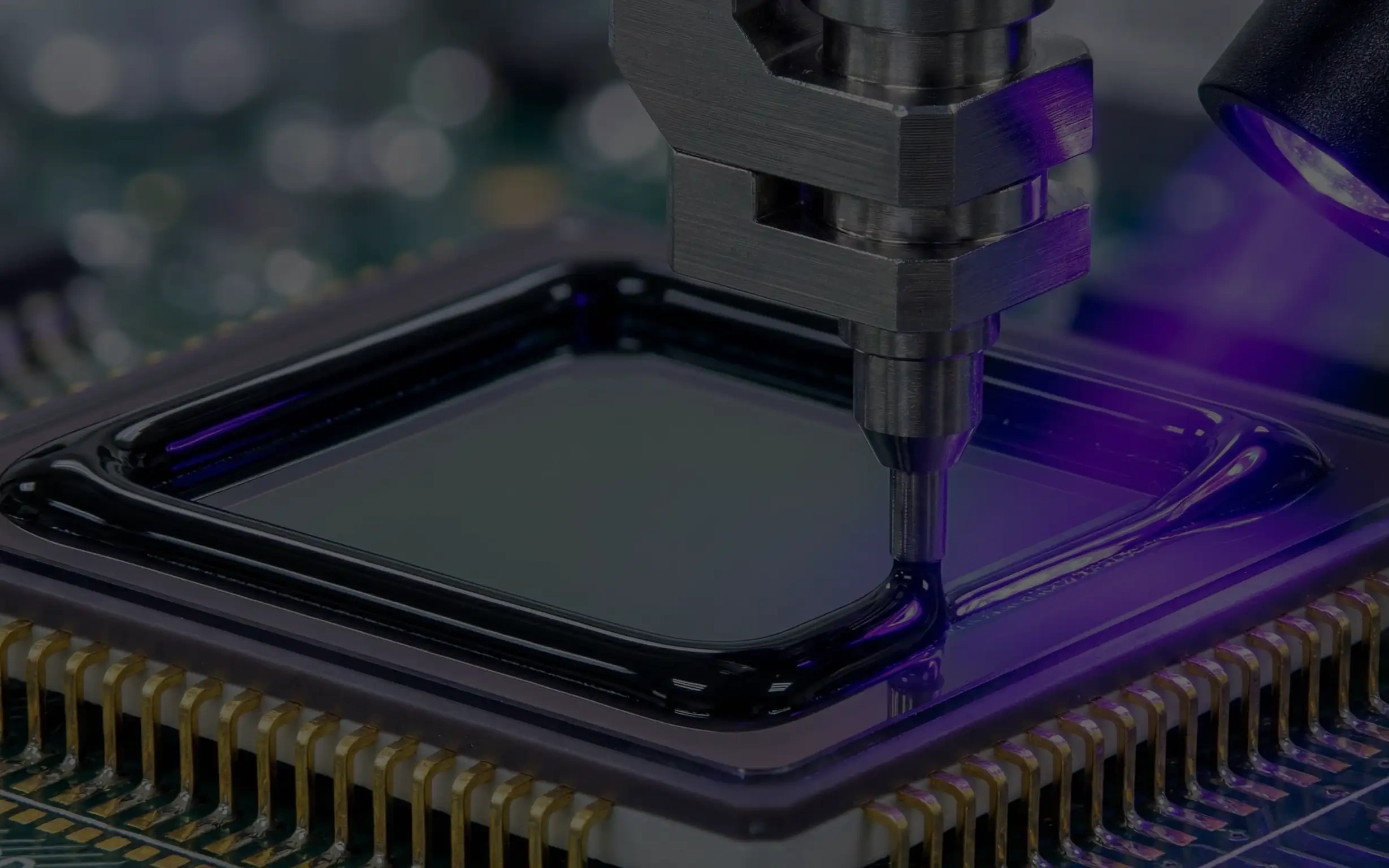
Verified by LED irradiation dose, the black light-shielding grade measures 1.5-2.0 mm of deep cure, enough for thick-section encapsulation in lamps and display modules.
UV-Thermal Dual Cure and Shadow-Zone Crosslinking
A shadow zone is set by structure; process can route around it but not remove it. UV-thermal dual cure turns light reachability from a yield condition into a process parameter you can set.
Where Shadow Zones Come From
Shadow zones turn up all over an assembly: under BGAs and components, inside metal shield cans, at the bend of a flex stiffener, beneath a thick black layer, and behind hidden steps inside a lens barrel. A single-cure UV system can only skin over in those places while the interior stays liquid, which means no structural strength and volatile species that expand during later high-temperature steps and contaminate optical surfaces. The misjudgment usually happens at inspection, where a tack-free surface is read as full cure and the real problem only surfaces downstream as a reliability failure.
Complementary Crosslinking and Degree-of-Cure Readout
SCITEO UV-thermal dual-cure systems carry a free-radical network and a latent thermal-cure epoxy network in one formulation, staged so each does a different job. Stage one cures the exposed region under UV in 2-3 s to build enough fixture strength for transfer. Stage two holds the assembly at 80-120 °C for 30-60 min in a tunnel oven, triggering latent epoxy ring-opening so shadow-zone adhesive reaches full crosslinking while already-illuminated regions crosslink a second time, the two networks interpenetrating. For lens modules and heat-sensitive plastics, a 50-80 °C trigger grade uses de-blocking kinetics to move the reaction into the low-temperature window.
Degree of cure has to come off an instrument. DSC residual reaction enthalpy converts directly into unreacted fraction and is the quantitative basis for shadow-zone cure; for filled, deeply colored systems, a hardness gradient profile and micro-FTIR conversion make useful complements. Measured along that path, degree of cure in shadow zones holds above 95%.
Interfacial Chemistry and Structural Strength
Acrylate networks are rigid with relatively few polar groups, so the interface relies on physical adsorption and mechanical interlocking, and adhesion decays irreversibly under long damp-heat aging. An epoxy backbone changes that: hydroxyl groups generated during cure form hydrogen bonds and chemical bonds with metal oxide layers, liquid crystal polymer (LCP) surfaces and FR-4 glass-epoxy boards, moving the interface from physical adsorption to chemical anchoring. Tested to GB/T 7124, dual-cure systems reach ≥20 MPa shear strength, two to three times a single-cure UV adhesive, which puts them in the structural bonding range.
Damp Heat, Thermal Cycling and Ion Control
The 85/85 damp-heat test (85 °C/85% RH) is the entry gate for automotive and industrial devices. Water diffuses into the adhesive along the free-volume network, elevated temperature accelerates hydrolysis, and the interface fails first at the edge fillet. SCITEO dual-cure systems compress the moisture permeation path with a densely crosslinked network and measure above 85% pull-force retention after 1000 h of 85/85 per JEDEC JESD22-A101. Thermal cycling follows JEDEC JESD22-A104 and thermal shock follows IEC 60068-2-14, both used to expose interfacial stress accumulation and micro-crack initiation.
The electrical side needs its own accounting. Under humid bias, free sodium and chloride ions migrate along the field and grow dendrites between closely spaced pads until insulation fails. Formulation control holds mobile ion content at or below 10 ppm, and ASTM E595 TML and CVCM limits constrain volatiles so optical surfaces and cavities stay clean.
Where It Lands: Application Interfaces
Material data only counts when it maps onto a real structure. The volume interfaces below are pushing light-cure materials to their limits.
Automotive Perception: ADAS Camera Modules and LiDAR
Automotive camera modules stack optical precision on top of automotive reliability inside one device. In forward, surround-view and rear-view modules, the lens assembly and sensor must hold alignment across a wide temperature range and under vibration, with material qualification aligned to AEC-Q100 temperature grades, 85/85, temperature cycling and thermal shock, and module-level sealing verified to IP69K. A single module hides several bond points you never see: IR-cut filter to lens holder, first-lens fixation, voice coil motor to housing, and moving parts inside periscope and variable-aperture structures, all of them constrained by low shrinkage and low outgassing at the same time. LiDAR leans more toward structure: the VCSEL or EEL emitter and the receive channel need high optical density isolation to suppress crosstalk, cavity walls need a low-reflection shielding layer against stray light, and the module's own alignment accuracy has moved into the sub-micron range, which makes it sensitive to both shrinkage and creep. SCITEO serves these interfaces with a low-shrinkage active-alignment grade for alignment locking and a black shielding grade for cavity and channel isolation.
XR and Micro-Displays: Waveguide Bonding and Optical Engine Assembly
Micro-display AR glasses (smart glasses, in everyday terms) have passed the million-unit mark, and microdisplay engines are moving from silicon OLED and LCoS toward Micro-LED, while optical routes migrate from glass diffractive waveguides toward high-refractive-index silicon carbide and geometric waveguides. That shift turns lens bonding and optical engine assembly into the yield bottleneck. Silicon carbide sits near a refractive index of 2.65, so a single layer can carry a wider field of view while the lens stays under 1 mm thick and a single lens element drops into the gram range, at the cost of heat-sensitive substrates and higher material price. The constraints here are compound: waveguide substrates and lenses are heat-sensitive, so the thermal budget has to stay low; the bonding layer needs low shrinkage and low birefringence because any cure displacement converts directly into image distortion; and stray light at waveguide edges and inside the optical engine has to be absorbed by a shielding layer to hold down rainbow artifacts and leakage. The material combination for this class is a low-modulus, low-shrinkage bonding grade, a black shielding grade, and a 50-80 °C trigger grade for heat-sensitive substrates. As nanoimprint waveguides enter volume production, the bonding layer also has to hold stable transmission and curing behavior from lot to lot.
Embodied AI: Humanoid Robot Vision and Tactile Modules
As embodied intelligence moves into volume production, a single humanoid robot typically carries several depth vision modules, and volumes scale with the platform for structured-light, iToF and dToF depth cameras, hand-eye cameras and tactile sensing arrays. What sets these modules apart is dynamic duty: the platform vibrates continuously while walking, grasping and absorbing impacts, so the module has to hold optical-axis stability at ever smaller size and weight. The adhesive needs enough modulus to resist vibration-induced displacement while staying compliant enough not to pass impact loads into the lens and sensor package. This class trends toward low-shrinkage, low-modulus stress-buffering formulations backed by 85/85 and thermal cycling data for long-service assessment.
Optical Interconnect and Advanced Packaging: Transceivers, CPO and Temporary Bonding
Optical interconnect is moving from pluggable transceivers to co-packaged optics, and once a single lane moves into the 200 Gb/s class, the optical engine and the switch die sit in the same package, so the electrical signal converts over a millimeter-scale path and the alignment tolerance for the optical path tightens with it. Cure shrinkage moves the coupling position directly; excessive modulus transmits stress into the optical engine, while insufficient modulus cannot hold collimation through thermal cycling, and fiber-array coupling to silicon photonic waveguides adds index matching and low birefringence to the requirement list. Shadow zones inside the shield can and under the engine are where dual cure finishes the job. On the wafer and panel side, light-cure materials enter the line as temporary bonding and debonding: they carry the device wafer through thinning, backside metallization and wet-process steps, then release by UV or laser with 5 s class curing, residue-free separation, and resistance to acids, bases and temperature. For the two shadow zones here, under the optical engine and inside the shield can, SCITEO's UV-thermal dual-cure structural grade completes the crosslinking.
Precision Medical and Industrial Inspection
Lens-stack cementing for single-use endoscopes, rigid borescopes and microscope objectives has to clear optical and biological requirements at the same time. Glass-to-stainless-steel bonds need high strength, index matching typically falls in the nd 1.47-1.65 window, and cure shrinkage moves the image plane directly, which ties low shrinkage and low birefringence to imaging quality rather than to cosmetic specifications. Sterilization adds real aging pressure: ethylene oxide, gamma irradiation, electron beam and autoclave steam all accelerate degradation of the crosslinked network, and ions or volatiles released onto an optical surface cannot be wiped away, which is why formulations for these devices are evaluated along ISO 10993 biocompatibility routes and paired with fluorescent tracers for in-line optical inspection. On the industrial side, machine-vision lenses, semiconductor inspection objectives and spectrometer optics carry the same low-outgassing and dimensional-stability requirements. SCITEO medical-grade formulations and low-temperature trigger grades cover lens-stack cementing, catheter fiber and sensor module assembly windows while holding low mobile ion content and low CVCM.
Line Integration, Verification and Selection Reference
Emission Matching and Dose Control
Confirm first that the photoinitiator absorption peak sits inside the UVLED emission band, with 395 nm or longer preferred for black and highly filled systems. Then establish a dose baseline: measure irradiance and cumulative dose at the dispense surface with a radiometer, plot depth of cure and degree of cure against dose, and select the window floor for the design bond-line thickness with margin above it. Finally, add lamp degradation checks to first-article confirmation, because falling dose at the adhesive surface shrinks deep cure directly.
Closing the Degree-of-Cure Loop
There is no conversion between a tack-free surface and degree of cure. First-article confirmation reads three values together: degree of cure from DSC residual reaction enthalpy, a Shore hardness gradient profile, and shear strength sampling at critical interfaces. All three have to pass; any drift sends the investigation back to dose and lamp state before anyone touches the formulation.
Dispensing, Fixtures and Shadow Compensation
Entrained micro-bubbles scatter light during cure and expand at elevated temperature, so a degassing-equipped high-precision screw valve or piezo jet valve is the better choice. High-takt lines increasingly move to non-contact jetting, where microliter-scale deposits put the rheological recovery and anti-slump behavior of the adhesive under closer scrutiny. Fixture design has to treat illumination angle as a variable: barrel depth and dispense path change the fraction of light that actually reaches the adhesive, and structures with heavy shadowing should rebalance the light-cure and heat-cure budget at design stage rather than at ramp. Thick black sections are best dispensed in layers with multiple exposures, so a single thick pass does not push the cure front past what the light source can deliver.
Selection Reference
| Process Interface | Typical Failure Mode | Key Metrics | SCITEO Direction |
|---|---|---|---|
| Active alignment and lens locking | Cure shift moves the optical axis, long-term creep drift | Volume shrinkage <0.6%, modulus window, Tg >150 °C, CTE <30 ppm/°C | Low-shrinkage chip-packaging UV adhesive |
| Black shielding and thick-section potting | Surface cured with liquid interior, cure gradient, uneven color | Red-shifted 395-405 nm absorption, depth of cure, OD and reflectance, DSC degree of cure | Black light-shielding deep-cure UV adhesive |
| Shadow zones and structural bonding | Liquid residue in dark areas, damp-heat interfacial delamination | Shadow-zone degree of cure >95%, shear ≥20 MPa, 1000 h 85/85 retention | UV-thermal dual-cure structural adhesive |
| Waveguide and heat-sensitive optic bonding | Cure shift induced distortion, thermal damage | Low shrinkage, low birefringence, 50-80 °C low-temperature trigger | Low-temperature dual-cure optical adhesive |
| Medical and optical cementing | Sterilization aging, ion release contaminating optical surfaces | ISO 10993 evaluation route, index matching, low birefringence, low-temperature cure | Medical-grade and low-temperature dual-cure optical adhesive |
| Wafer and panel-level temporary protection | Debonding residue, acid and base attack | UV/laser debonding, chemical resistance, residue-free release | Temporary bonding and masking UV adhesive |
Conclusion
From sub-micron alignment in automotive perception to optical-path locking in micro-display engines and co-packaged optics, light-cure materials have moved from consumable to the interface layer that decides yield. Whether shift during cure can be predicted, whether degree of cure inside a shielded thick layer can be measured, and whether interfacial strength in shadow zones and damp-heat service can be audited decide whether a material actually reaches the process. SCITEO Advanced Materials organizes its formulation platforms along photochemical fundamentals, covering chip packaging, black light shielding and UV-thermal dual cure with low-shrinkage architectures, red-shifted initiators with nano-graded shielding filler, and a low-temperature-triggerable thermal network, and it defines process windows across dispensing, exposure, post-cure and first-article inspection.
This article is SCITEO Advanced Materials original technical content; unauthorized reproduction is prohibited.
Appendix: Process & Engineering Adhesive FAQ Index
Deep-dispensed black light-shielding adhesive keeps curing at the surface while the interior stays liquid. What is the physical root cause, and what actually fixes it?
Dual attenuation is the root cause. Carbon black runs 10-100 nm as primary particles with 100-500 nm aggregates, and that enormous surface area gives it a molar absorption coefficient at 365 nm well above its visible-range value, so photon energy decays exponentially within tens of microns and the deep initiator never gets a chance to cleave. The fix starts in photochemistry: red-shift initiator absorption to 395-405 nm for deeper penetration, choose photobleaching chemistries whose absorption drops as the initiator is consumed, and use nano-graded shielding filler that holds optical density above 3 while keeping one controlled scattering channel in the near-UV band. Verified by LED irradiation dose, these black systems reach 1.5-2.0 mm of deep cure with coating reflectance below 2%.
How does a UV adhesive guarantee complete crosslinking in shadow zones under components or inside shield cans?
A shadow zone is set by structure, so process cannot remove it. The cure mechanism has to change instead, which means a UV-thermal dual-cure interpenetrating network. Exposed adhesive builds fixture strength under UV in 2-3 s so the assembly can move on right away, while shadow-zone adhesive is driven by a later 80-120 °C thermal field that triggers latent epoxy ring-opening, and already-illuminated regions crosslink a second time. Degree of cure is never judged by surface tack; it is read from DSC residual reaction enthalpy and holds above 95% in shadow zones, with shear strength two to three times that of a single-cure UV adhesive.
What causes optical-axis shift at the instant of UV cure during active alignment, and how is it quantified?
Three terms add up: free-volume collapse as intermolecular distances compress from the van der Waals scale to covalent bond length, incomplete volume compensation from ring-opening polymerization, and the polymerization exotherm followed by cooldown contraction. Under an isotropic approximation, linear shrinkage is about one third of volume shrinkage, and shift equals linear shrinkage multiplied by bond-line thickness. A 50 μm bond line at 4% volume shrinkage gives roughly 0.65 μm of axial shift, and thickening to 150 μm pushes shift into the 2 μm class, enough to eat a full 1 μm pixel. SCITEO chip-packaging UV grades use a specialty macromolecular oligomer and low-shrinkage monomer architecture to hold volume shrinkage below 0.6% and linear shrinkage below 0.2%, which brings shift into the 0.1-0.3 μm range at the same geometry.
How do you balance the thermal cure temperature in shadow zones against heat-sensitive components?
Start by identifying where the temperature limit actually comes from. Lenses, voice coil motors and flex circuits are usually limited by glass transition and creep behavior, not by solder reflow tolerance. Dual-cure systems typically offer two thermal trigger windows: an 80-120 °C main grade for metal shield cans, BGA underfill and structural parts, where higher crosslink density is wanted; and a 50-80 °C grade for lens modules and heat-sensitive plastics, where de-blocking kinetics move crosslinking into the low-temperature window. Control the process on hold time measured by a thermocouple inside the assembly, not on oven setpoint, and add an equalization ramp ahead of the hold for mixed assemblies.
Once the UV LED wavelength is fixed, how does a line hold dose and degree of cure?
LED heads emit a narrow band, so the photoinitiator absorption peak has to sit inside it; otherwise more dose still only skins the surface. Black and highly filled systems call for 395 nm or longer. Three items belong in daily dose control: measure irradiance (mW/cm²) and cumulative dose (mJ/cm²) at the dispense surface with a radiometer instead of trusting the head's rated power; keep lamp degradation checks in first-article confirmation, because falling dose at the adhesive surface shrinks deep cure directly; and verify degree of cure by DSC residual reaction enthalpy or a hardness gradient profile, since surface tack has no conversion to degree of cure and hand-feel cannot replace instrumented readout.
The same UV adhesive passes in the lab but fails in batches on the production line. What usually changes?
Causes usually split across three chains, and troubleshooting works best in order. Light-path geometry moves first: once fixture shadowing, barrel depth or dispense path changes, the incident angle no longer matches a flat lab exposure and the shadow fraction climbs. Source state comes second, where lamp degradation, contaminated quartz windows and conveyor speed drift stack into a cumulative dose that quietly falls below threshold. Material is the third, because a shielding-filler supplier or lot change alters particle size and dispersion and amplifies into a depth-of-cure shift that follows an exponential, not a linear, response. Bind dose verification, first-article degree-of-cure profiles and incoming particle-size characterization into one release checklist, and rerun depth-of-cure validation after any change. That is far more reliable than reviewing appearance after the fact.