From 3nm GAAFET to CoWoS-L Heterogeneous Integration: Wafer-Bond Cleanliness, Thermal Stress and Interface Material Failures
SCITEO walks the chain from front-end fabrication to finished system, segment by segment, mapping the process window that adhesives must hold across backside power delivery, through-silicon vias, HBM4 stacks, kW-class liquid cooling and co-packaged optics
Abstract
The yield ceiling in AI silicon left the lithography scanner a while ago. It now sits at the interfaces buried inside the package. At 3nm and 2nm, GAAFET architectures sculpt channels only tens of atoms thick, and CoWoS-L, HBM4 and hybrid bonding reassemble those transistors into multi-kilowatt packages. Whether that chain reaches volume production comes down to how wafer temporary-bond adhesives, underfill, thermal interface materials and conductive adhesives hold the thermo-mechanical and chemical line under extreme temperature, sub-nanometer cleanliness and multi-axis shear. SCITEO Advanced Materials works this problem from the interface side. This article follows the chain from wafer front end to finished system: the material temperature ceiling in front-end processing and backside power delivery, the cleanliness and yield economics of TSV and hybrid bonding, CTE mismatch and underfill rheology in CoWoS-L and panel-level packaging, TIM1 pump-out in kW-class accelerators, and sub-micron alignment in co-packaged optics.
Bottom line: the performance gain from node scaling is ultimately realized at the thermo-mechanical and chemical boundaries of the interface material.
Core Parameter Comparison
The table below puts SCITEO semiconductor-process adhesives and industry-typical auxiliary adhesives on the same measurement basis. The last column doubles as a review checklist:
| Parameter | SCITEO Solution | Industry Typical | Test Standard |
|---|---|---|---|
| Applicable process node | 3nm GAAFET / CoWoS-L | 28nm and above | n/a |
| Extreme process temperature | 300-500 °C | 150-200 °C | TGA / long-term heat aging |
| Interposer scale | 5.5× reticle (volume generation) | 1-2× reticle | n/a |
| Underfill Tg | 100-155 °C | 80-120 °C | DMA |
| Underfill CTE | <30 ppm/°C (min. 13 ppm/°C) | 50-80 ppm/°C | TMA |
| TIM1 thermal conductivity | 20-40 W/m·K | 1-3 W/m·K | ASTM D5470 |
| Die-attach shear strength | 30 MPa | 5-10 MPa | GB/T 7124 |
| Conductive adhesive shear strength | 19 MPa | 5-10 MPa | GB/T 7124 |
| Volume resistivity | >10¹⁴ Ω·cm | 10¹²-10¹³ Ω·cm | ASTM D257 |
| TIM1 CTE | <20 ppm/°C | >50 ppm/°C | TMA |
| Extractable ion content | ≤10 ppm (Na⁺/Cl⁻) | 30-100 ppm | IC ion chromatography |
I. Wafer Front-End (FEOL): 3nm GAAFET, Backside Power Delivery and the Temperature Ceiling of High-Aspect-Ratio Etching
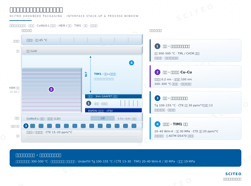
Front-end processing sets both the intrinsic performance of the transistor and the process window available to auxiliary materials. At 3nm/2nm, GAAFET nanosheets, EUV multi-patterning, high-aspect-ratio etching and backside power delivery stack on top of each other, pushing vacuum residence time, transient heat flux and outgassing risk upward together. For wafer temporary-bond adhesives, hardmask adhesives and probe-card fabrication, the temperature ceiling, total mass loss (TML) and collected volatile condensable materials (CVCM) stopped being options a while ago. They are yield constraints. On customer lines we have traced plenty of defects that looked like equipment problems back to the heat resistance and outgassing of a single adhesive layer.
From FinFET to GAAFET: Why Channel Control Changed Hands
As nodes move from 5nm toward 3nm and 2nm, the three-sided FinFET gate loses electrostatic control of the channel, and short-channel effects and leakage current climb together. The industry moved to Gate-All-Around (GAAFET) and nanosheet architectures, wrapping the gate around the channel on all four sides to take control back. EUV lithography is the enabling process, but it also drives high-energy plasma bombardment and localized thermal load straight into the wafer surface, and that load propagates down through the wafer thickness into the temporary-bond interface, where it becomes one source of downstream yield variation.
The next stop for gate control is already on the roadmap. Complementary FET (CFET) stacks NMOS over PMOS to take another step out of cell area: at the latest VLSI Symposium Intel showed a monolithic CFET inverter at 45 nm gate pitch with PowerVia and direct backside contacts, Samsung demonstrated triple-stacked nanosheet channels at 42 nm gate pitch, and TSMC pushed a monolithic CFET ring oscillator below 48 nm at IEDM and demonstrated the smallest 6T SRAM of its time. Once devices go vertical, both the nanoscale topography budget on the wafer surface and the cleanliness budget at the bond interface tighten again.
Backside Power Delivery (BSPDN): Moving the Power Network Behind the Wafer
Below 2nm, power and signal interconnects compete for the same limited front-side metal layers, and routing congestion together with IR drop become design constraints. A backside power delivery network (BSPDN) moves the power network to the back of the wafer and frees the front side entirely for signal routing.
Intel's PowerVia entered volume production with Intel 18A, and the latest VLSI Symposium produced the most complete accounting to date: up to 11% block-level area reduction, a 10x cut in worst-case dynamic voltage droop, and up to 6% higher frequency or more than 15% lower dynamic power. The follow-on Intel 18A-P is in risk production at more than 9% higher performance at iso-power or more than 18% lower power at iso-performance, with materials and design work pulling thermal resistance down 20%-40%; the 3DIC-oriented 18A-PT folds through-silicon vias, die-to-die interconnects and an industry-leading-pitch hybrid bonding interface (HBI) into the base die for up to 9x higher die-to-die bandwidth density, with risk production already scheduled. TSMC introduced Super Power Rail (SPR) at its A16 node, tying backside contacts directly to transistor source and drain to preserve N2P gate density, and targets 8%-10% higher speed at equal power, 15%-20% lower power at equal speed and roughly 1.10x chip density, with volume production already locked; the second-generation backside power rail lands on A12, the A14 platform enhancement, with A14 and A13 following after it.
This route imposes new constraints on auxiliary materials. The BSPDN flow adds wafer-to-wafer bonding, extreme thinning, backside alignment, nano-scale through-silicon via (nTSV) etching and backside metallization; once a wafer is thinned to a few tens of microns, its stiffness collapses and the temporary bond line becomes the only source of mechanical support, while backside alignment error translates directly into higher contact resistance and can open the circuit outright. Whether the bond line's CTE and modulus match silicon determines the warpage of the thinned wafer, and warpage then compounds into overlay error in later lithography and bonding steps.
CVD/PVD, Ion Implantation and Rapid Thermal Processing
Forming transistor source/drain regions and depositing insulating dielectric layers relies on chemical vapor deposition (CVD) and physical vapor deposition (PVD); post-implant rapid thermal processing (RTP) demands extreme temperature to activate dopants and repair lattice damage.
In these wafer-grade high-temperature steps, temporary wafer bonding, hardmask shielding and probe-card fabrication all constrain the heat tolerance of auxiliary materials. Conventional high-temperature adhesives carbonize and volatilize quickly at these temperatures, generating outgassing contamination; the industry quantifies that risk through ASTM E595 total mass loss (TML) and collected volatile condensable materials (CVCM), where a lower CVCM means a lower probability of contaminating chambers and probes. Leading fabs adopt SCITEO chip-process high-temperature adhesives (300-500 °C) in front-end and burn-in steps because the bond line still holds structural integrity alongside its insulating or conductive behavior after extreme thermal shock. Worth noting: these temperature, TML and CVCM figures are not a line item in a catalog. They are formulation windows built around a customer's chamber ambient, ramp rate and dwell time, which is why a development-oriented supplier would rather join the process definition early.
High-Aspect-Ratio Etching and Plasma Bombardment
During GAAFET nanosheet release, deep-trench isolation and damascene trench etching, engineers face extreme aspect-ratio-dependent etching (ARDE). The deeper the hole, the slower the etch rate, until the bottom shows profile deformation or micro-trenching, while high-energy plasma adds violent localized heating. The higher the aspect ratio, the more the hardmask adhesive has to hold pattern edges and thickness uniformity under combined ion bombardment and temperature rise, because any softening or flow writes itself straight into the etch profile. Mask materials are therefore specified on transient temperature rating, plasma-etch resistance and low volatility as a set, not on a single long-term temperature figure.
II. Middle-End (MEOL): TSV, Hybrid Bonding and Sub-Nanometer Cleanliness
When a single die approaches the reticle limit (roughly 850 mm²), yield falls off nonlinearly with area, which is why the industry turned to chiplet disaggregation and advanced packaging. Middle-end processing delivers the vertical interconnect: TSVs drill through silicon and fill with copper, while hybrid bonding joins copper and oxide directly at atomic scale. Yield in this segment is not set by equipment accuracy alone, but by interface cleanliness, surface flatness and the chemical identity of residue.
TSV (Through-Silicon Via) and Silicon Interposer
To interconnect GPU and HBM vertically at high bandwidth on a silicon interposer, the wafer must be drilled through and filled with copper. The most common TSV etching defect is a scalloped sidewall, which leads to uneven deposition of the subsequent insulation and barrier layers and plants a leakage risk. In later thermal steps, expanding copper pillars squeeze the surrounding silicon into micro-cracked stress zones. That is one of the core causes of middle-end yield loss.
Interconnect generations are, at heart, one curve of shrinking and densifying connection points:
| Interconnect Generation | Typical Pitch | Physical Limit |
|---|---|---|
| Wire Bonding | ≈100 μm | Low bandwidth, high latency; survives only in low-end devices |
| Flip Chip | 100-150 μm | Solder-ball size caps density growth |
| Micro-bump | 40 μm tightening toward 10 μm | Below a minimum solder volume, shorts, opens and assembly yield deteriorate sharply |
| Hybrid Bonding | 6 μm at the production edge (sub-micron demonstrated in research) | Sub-nanometer cleanliness, 0.2 nm surface roughness and sub-100 nm alignment |
Hybrid Bonding: After Pitch Passes 6 Micrometers
Mainstream interconnects still rely on micro-bumps, but their pitch stalls in the tens of microns. For denser 3D stacking, whether HBM die stacks or SRAM-on-logic, the industry is moving to bump-less Cu-Cu hybrid bonding. TSMC walked its SoIC bond pitch from 9 μm to 6 μm, with 4.5 μm on the roadmap; Intel has Foveros Direct shipping in Clearwater Forest server processors, and AMD has run the process in volume since its first 3D V-Cache parts. The density gain is order-of-magnitude: face-to-face hybrid bonding provides on the order of 14,000 signal connections per square millimeter, against roughly 1,500 per square millimeter for face-to-back through-silicon-via stacking.
The interface requirements are severe. Wafer surfaces must reach atomic-level flatness, with the polished dielectric held within roughly 0.2 nm and copper pads sitting a few nanometers below it, then adhere at room temperature by van der Waals force before a 200-300 °C anneal lets copper expansion close the gap. Alignment must reach sub-100 nanometer accuracy and particle contamination must be near zero. A single particle 100 nm across is enough to prevent bonding across an entire region. On process architecture, wafer-to-wafer bonding aligns once at wafer scale for the tightest pitch and fastest output, at the cost of requiring identically sized dies and bonding defective ones along with good ones; imec and EV Group demonstrated a 200 nm wafer-to-wafer pitch with post-bond overlay below 40 nm at ECTC. Die-to-wafer bonding allows test-before-place and mixes die sizes and process nodes, but picks and aligns every die individually: CEA-Leti showed the best die-to-wafer result at ECTC, at 1 μm, bonders run at roughly 1,600 to 2,000 die placements per hour, and the next platform generation is pushing placement accuracy toward 50 nm.
Pitch benchmarks on the research side keep moving too. At the latest ECTC, Applied Materials demonstrated the first 450 nm-pitch Cu-Cu hybrid bonding with 98% yield across 20 million interconnects, and traced the opens to a thin carbon-rich layer at the bond interface together with copper grain orientation. That result moves hybrid-bond yield control from particle counting to interface chemistry: what decides an open is the make-up of the residue and the orientation of the copper grains, not the particle count alone.
This is why temporary-bonding and masking adhesives must debond with zero residue: any microscopic organic remnant expands into a macroscopic void during annealing and open-circuits the die stack, and the chemical identity of a residue often only surfaces after annealing, in the form of a failure. On the memory side, JEDEC raised the high-bandwidth memory package thickness ceiling from 720 μm to 775 μm, which restored thickness headroom to micro-bump assembly. SK hynix gave the latest read at Hot Chips: hybrid bonding will not be ready for HBM4E and slips to HBM5 at the earliest, so 12-Hi stacks stay in volume production, 16-Hi (48 GB per cube) sits in customer qualification with core dies thinned to roughly 50 μm and inter-layer gaps halved against 12-Hi, and thermocompression bonding (TCB) with mass reflow molded underfill (MR-MUF) keeps carrying the main flow. Pin speed has climbed from 1 Gbps on the original HBM to 8 Gbps on HBM4 and is now heading for 16 Gbps on HBM4E, which pushes the stack to about 2.2x the thermal load of earlier generations and leaves the material budget thinner rather than thicker. Heat is therefore being addressed inside the stack: SK hynix's iHBM embeds electrically insulating thermal conductors in the die-to-die PHY layer, claimed to cut thermal resistance by more than 30%, while Samsung's HPB runs its own heat path, both targeted from HBM5. The company's own roadmap shows that moving 20-Hi to hybrid bonding would allow core dies up to 24% thicker, thermal resistance roughly 35% lower than MR-MUF and bump pitch below 18 μm, and the industry is already discussing an 825-900 μm thickness budget for those stacks. The hard constraints of sub-nanometer cleanliness and sub-100 nm alignment, meanwhile, are already written into the next process list.
Yield Economics: CMP Drift, Queue Time and KGD Screening
Hybrid-bond yield is not decided by a single step but by several coupled process windows. Hybrid bonding depends on nanoscale topography control across copper pads and dielectric on one plane: chemical mechanical polishing (CMP) deliberately leaves a slight copper protrusion and dielectric recess so that copper expansion closes the gap during anneal. The problem is that CMP nano-topography drifts over time. If the dielectric sits too high, copper never connects; if copper sits too high, voids form. Both deviations land directly on yield, and without post-CMP metrology and a rework loop, small variation cascades into batch-scale loss.
Another constraint is queue time and moisture uptake: if too long elapses between polish and bonding, the dielectric adsorbs moisture, bond-interface strength drops and copper pads face corrosion risk. The third is known-good-die (KGD) screening. Wafer-to-wafer bonding pairs every die on both wafers, so one bad die scraps the whole pair; die-to-wafer bonding allows test-before-place, but each die is picked, aligned and placed individually, which turns bonder throughput into the new bottleneck. The gap between the finest wafer-level pitch and the achievable die-level pitch is therefore set by process reality: a sub-micron demonstration at wafer level does not imply volume capability at die level. In our experience, deviations inside a process window rarely show up alone; CMP drift, queue-time overrun and KGD coverage tend to degrade together. The review question worth asking is which of the three loses control first, not what any single parameter reads.
For materials, these three constraints converge on one set of metrics: control of extractable ions and organic residue, particle cleanliness after debonding, and thermal stability across the entire bond flow. SCITEO's temporary-bond and masking adhesives land on that same set of metrics, and debond residue-free.
III. Back-End Process and Packaging (BEOL): From RC Delay to CoWoS-L and Panel-Level Packaging
Back-end processing resolves the tension between signal transmission efficiency and structural integrity. Shrinking linewidth raises RC delay while low-k dielectrics sacrifice mechanical strength, and assembling expensive chiplets onto organic substrates introduces CTE mismatch. The larger the package, the more interfaces it contains and the thinner the stress budget left to each one. That is what moved underfill and thermal interface materials from consumables to structural materials.
RC Delay and CMP Polishing
As linewidth shrinks, the cross-sectional area of copper interconnects plummets and resistance (R) soars, while narrowing spacing drives parasitic capacitance (C) up; RC delay is now the leading physical bottleneck on AI chip clock frequency, and to cut capacitance the industry introduced ultra-low-k dielectrics that are riddled with micropores and mechanically fragile. Copper's own resistance ceiling is forcing new options as well: the subtractive ruthenium with air-gap integration Intel demonstrated at the VLSI Symposium cuts interconnect capacitance by roughly another 35%, buying headroom as metal pitch keeps shrinking.
During CMP, fragile low-k layers readily develop micro-cracks, delamination, copper dishing and dielectric erosion. For processes that hold ultra-thin wafers by temporary bonding, slurry impingement and downforce shear test the bond line the same way: insufficient bond strength lets the wafer slip mid-polish, and adhesive residue turns into particle defects during subsequent cleaning.
CTE Mismatch and Solder-Joint Fracture
Assembling expensive chiplets onto organic substrates is the decisive stage of the packaging yield game. Silicon's CTE is about 2.6 ppm/°C while the glass-fiber resin substrate runs several times higher (~15-20 ppm/°C); as the package passes through 260 °C lead-free reflow and cools to room temperature, the mismatch in contraction accumulates enormous shear stress that tears the micro-bumps at the chip edge apart.
Capillary Rheology of Underfill
Resisting that tear means injecting underfill into a chip-to-substrate gap only tens of microns wide, where the material needs extreme capillary flow and zero bubble voids inside the bump array. SCITEO's advanced underfill cures into a three-dimensional network with high Tg (100-155 °C, DMA) and low CTE (<30 ppm/°C, minimum 13 ppm/°C, TMA), spreading the lethal shear concentrated on micro-bumps across the whole package interface and multiplying board-level thermal-cycle (TCoB) life. In review, Tg and CTE must be checked as a pair alongside cure shrinkage and extractable ion content: the first determines whether residual cure stress pulls apart fragile low-k structures, the second how long insulation performance survives in a humid, biased environment.
CoWoS-L and Panel-Level Packaging: After Interface Counts Double
Advanced packaging platforms split into three interposer routes, silicon interposer (CoWoS-S), redistribution layer (CoWoS-R) and local silicon interconnect (CoWoS-L), which map to routing-density-first, cost-first and very-large-package-first design priorities respectively. Flagship AI accelerators broadly adopt the local silicon interconnect route, stitching multiple logic dies into one package with local silicon bridges, which raises both the number of HBM stacks the package can carry and per-GPU memory bandwidth; bridges stacked on top of interposer and organic substrate multiply the number of interfaces, and with them the accumulated CTE mismatch. TSMC's size roadmap puts numbers on that constraint: 3.5x-reticle CoWoS-L is in production, the 5.5x-reticle version qualified and entered volume production, and a 14-reticle version is on the roadmap to carry roughly 10 large compute dies and 20 HBM stacks, with further expansion to larger formats alongside the 40-reticle SoW-X system-on-wafer.
The next step changes the package format itself. Panel-level packaging replaces the round wafer with a rectangular panel, raising area utilization substantially while compressing cost per unit area, and glass-core substrates replace the organic core with glass whose CTE can be tuned, with through-glass vias (TGV) carrying vertical interconnect and heat paths, improving mechanical rigidity and dielectric loss at the same time. Both routes compress more interfaces into a larger package body, which makes wetting, adhesion and stress-buffering capability first-order variables for interface materials.
IV. High-Compute Power, Liquid Cooling and Optical Interconnect
Climbing compute demand brings sharply expanding heat density. Power consumption of a single high-end AI chip has entered the kilowatt range and rack-level power has risen to the point where full liquid cooling is mandatory, while cooling and interconnect both retreat further inside the package.
Interface Thermal Resistance and TIM1 Pump-Out
A chip that cannot move heat to the vapor chamber or cold plate above will thermal-throttle and lose throughput. The TIM1 layer between bare die and lid is the critical limiting element in that heat path, and under the high-frequency pump-out of thermal expansion and contraction, ordinary thermal materials pulverize and delaminate.
For high-flux loads, SCITEO chip-attach thermal adhesives combine high-density filler grading with polymer interfacial coupling. The result is low interface thermal resistance alongside 20-40 W/m·K conductivity (ASTM D5470), 30 MPa shear strength (GB/T 7124) and <20 ppm/°C CTE (TMA). Those numbers sit where they do for a reason. Conventional polymer TIMs conduct only 3-6 W/m·K, and in a 600 W-class module a single low-conductivity interface accounts for roughly 10 °C of temperature rise; liquid-metal approaches push interface resistance down to 0.01-0.025 °C·cm²/W but bring containment and galvanic-corrosion risk. Pump-out resistance turns on matrix modulus, and the practical window sits around 0.1-2.0 MPa of crosslink-controlled stiffness, enough cohesive strength to resist shear deformation while staying compliant on a rough surface. Repeated first-party ASTM D5470 measurements at SCITEO show that conductivity for the same formulation drifts with test pressure and bondline thickness, so reviews must re-measure interfacial thermal resistance at the target pressure and thickness.
Signal Purity in RF Front-Ends and Fine Interconnects
For communication basebands, RF front-end modules, and system-in-packages (SiP) that cannot survive high-temperature reflow, conventional soldering risks bridging shorts or thermal damage. SCITEO chip conductive adhesives, built on percolation theory, control tight silver-flake packing and ultra-low ionic impurity to deliver 19 MPa bond strength (GB/T 7124) while forming a low-impedance ohmic contact network. High-frequency, high-speed signals get a clean path.
What actually decides whether the material reaches millimeter-wave and high-speed links is everything around the conductive skeleton. Extractable ions (Na⁺, Cl⁻) migrate along the field under humid bias and grow dendrites between fine-pitch pads, and silver itself joins electrochemical migration in ionic form. Holding ion content below 10 ppm and cure shrinkage low keeps contact resistance from drifting through thermal cycling, because at 200 Gb/s per lane, impedance drift at a single joint eventually shows up as insertion loss and eye-margin budget, and that budget is allocated in fractions of a decibel. That is why conductive adhesives keep displacing solder in optical module COS assembly, RF front-end modules, power modules and MEMS packaging: the interconnect stops being a soldering-metallurgy problem and becomes a formulation-chemistry problem, which preserves design freedom as packages shrink and integrate heterogeneous dies.
AI Training Servers: The Interface Loop of HBM4 Stacking and kW-Class Liquid Cooling
Return the interface-thermal-resistance and signal-integrity requirements to a real system and AI training servers become the most demanding proving ground available. Inside a rack-scale architecture, the HBM stacks and CoWoS-L interposer on one GPU substrate form a multi-interface structure in which total CTE mismatch is amplified several times over. As training load swings between full and idle at high frequency, the whole interposer endures violent thermal cycling, and the interface that delaminates first is usually the under-strength die-attach bond. Once an HBM channel drops out, training throughput degrades immediately and visibly.
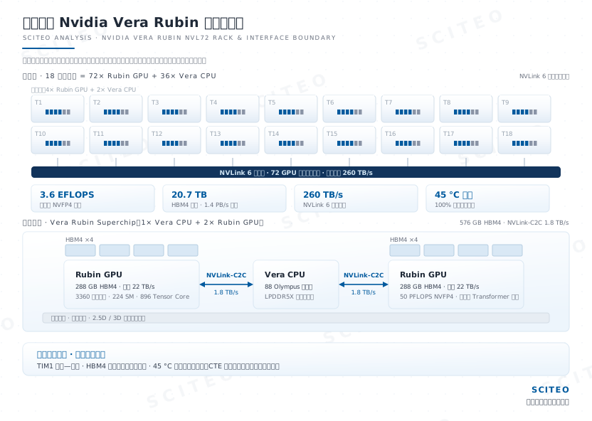
The cooling transition tightens the material window further. Per-GPU thermal design power has climbed from 400 W on A100 to the 2.3 kW class in the Vera Rubin generation, and a single DGX Rubin NVL72 rack draws roughly 227 kW at its maximum-performance operating point. Air cooling is out: the Rubin generation runs 100% liquid-cooled with a 45 °C warm-water inlet, trading a higher cold-plate temperature for year-round free cooling. Liquid cold plates remove heat from the lid, but they also widen the temperature gradient between bare die and lid, which is what aggravates TIM1 pump-out. SCITEO counters with a high-modulus thermal interface material and distributes shear across the stacked interfaces with low-CTE underfill, holding interface thermal resistance stable over long service life. The in-stack heat path described earlier is the other preparation made along this route; once heat is pulled out from inside the stack early, the interface material at the bottom of the package no longer carries the whole thermal budget alone, and that new heat path belongs in the selection review.
Co-Packaged Optics (CPO): Sub-Micron Alignment as a New Material Threshold
Optical interconnect is moving off the faceplate and into the package. Pluggable optical modules require electrical signals to travel more than ten centimeters along the printed circuit board before electro-optical conversion; once per-lane rates reach the 200 Gb/s class, high-frequency attenuation, dielectric loss and reflections deteriorate together, capping both power efficiency and port density. Co-packaged optics (CPO) places the silicon photonics engine and the switch ASIC on the same package substrate so that conversion happens within millimeters of the die. NVIDIA put its Spectrum-X Ethernet Photonics switch into full volume production, billed as the first 200G-per-lane CPO Ethernet switching system to ship, with 102.4 Tb/s of switching capacity per chip; paired with an external laser source architecture, that works out to roughly three-quarters fewer lasers, 5x better network power efficiency and 10x better mean time between failures, with optical loss falling from roughly 22 dB to about 4 dB. TSMC's COUPE-on-substrate has also entered production, integrating the optical engine inside the package for 2x better power efficiency and 10x lower latency than a pluggable module on the board. Near-packaged optics (NPO) is landing first on serviceability: Huawei announced its Ascend 960 supernode at the latest HUAWEI CONNECT, replacing the 48,000 800G pluggable modules that would normally be needed with 5,500 in-house NPO optical engines (Hi-ONE, 7.2 Tbit/s each), cutting system power by more than 550 kW at 99.8% system availability. Both routes coexisting is already the customer-side reality, and 409.6T switching will be the physical inflection point for pluggables.
When the optical engine and the switch ASIC share one package, sub-micron optical alignment tolerance becomes a new item on the interface material's test sheet. Cure shrinkage moves the coupling position directly; a modulus that is too high transmits stress into the optical engine, and one that is too low cannot hold alignment through thermal cycling. SCITEO's low-shrinkage, low-modulus stress-buffering formulations for optical semiconductor packaging are the technical headroom reserved for these co-packaged structures.
V. Four Coordinates on the Packaging Roadmap
The packaging roadmap is clear enough, and several coordinates deserve advance preparation from anyone working in interface materials.
Bridge architectures are replacing full interposers. Embedded multi-die interconnect bridges have advanced to the through-silicon-via generation, EMIB-T. Intel's numbers from ECTC: 36 μm bump pitch on a package carrying 2× reticle-sized silicon, a 65% bump-density gain over the 45 μm pitch used in Granite Rapids, with validation expanding toward 4.5x reticle scale and a certification milestone already scheduled. A single 3 mm × 18 mm bridge already ties two one-reticle dies together at 25 μm pitch, and below 25 μm the limit shifts from bridge routing density to bump formation, placement accuracy and assembly yield. On-bridge TSVs deliver power vertically through the bridge and cut DC voltage drop 68%-80% against conventional EMIB, and the integrated MIM capacitors reach 500 nF/mm². Quarter-panel test vehicles measure 240 mm × 240 mm, roughly 67 reticles of area, where warpage now sits alongside routing density as a first-order constraint. The larger the package, the thinner the stress budget left to the interface.
Glass substrates are leaving the lab. At NEPCON Japan Intel showed a full-size 78 mm × 77 mm glass-core substrate prototype: a 10-2-10 stack of twenty routing layers around an 800 μm glass core, 45 μm bump pitch and roughly 1,716 mm² of silicon attach area, about 2× reticle, with the company stating that dicing and handling micro-cracking is resolved. Glass sits closer to silicon in CTE and warps less, but surface metallization and fine-line patterning are still climbing the maturity curve, so commercialization will most likely follow sampling, qualification and then volume production. Glass raises the bar on wetting and adhesion for interface materials, which gives low-temperature cure systems additional engineering value.
Panel-level packaging is rewriting area economics, one size down. Carrier formats under development span 310 mm × 310 mm, 510 mm × 515 mm and 600 mm × 600 mm, and TSMC's CoPoS anchors first on 310 mm × 310 mm for pilot production, leaving 510 mm × 515 mm for the glass-core generation. The appeal of a larger panel is unit cost; the risk is warpage, uniformity and stitching accuracy, so the volume window lands in the next two to three years.
Quantum computing has pushed the temperature domain to millikelvin. Chip-scale scalable photonic quantum computers and superconducting routes both impose extreme requirements on cryogenic interfaces: low-temperature embrittlement, multi-material CTE mismatch and ultra-low outgassing must hold simultaneously. That mirrors the constraints of high-temperature processing and tests the elasticity of one formulation platform across both ends of the temperature range.
SCITEO's view is that these directions will not all become purchase orders at the same time, but they determine the formulation redundancy a material platform should carry. SCITEO's application team tracks these frontier processes continuously and adjusts development priorities across the high-temperature, thermal-conduction and low-stress product lines accordingly.
VI. Interface Material Selection Quick Reference by Process Segment
The table below compresses the mechanisms above into executable selection points for process engineers to check during design review:
| Process Segment | Typical Failure Mode | Key Metrics | SCITEO Direction |
|---|---|---|---|
| Wafer temporary bonding and backside thinning | Chamber contamination from outgassing, warpage after thinning, debond residue | TML/CVCM, temperature rating, CTE matching, zero-residue debonding | Chip-process high-temperature adhesives (300-500 °C) |
| High-aspect-ratio etch hardmask | Bond line softening and flow, pattern shift | Transient temperature rating, plasma resistance, low volatility | Chip-process high-temperature adhesives |
| TSV and hybrid bonding | Bond voids from particles and organic residue | Sub-nanometer cleanliness, extractable ion content, debond residue | Temporary-bond and masking adhesives (zero-residue debonding) |
| Flip-chip underfill | Voids, delamination, solder-joint fatigue | Tg 100-155 °C, CTE <30 ppm/°C, capillary flow | Chip encapsulation adhesives (underfill) |
| Die attach and thermal interface | TIM1 pump-out, drifting interface thermal resistance | 20-40 W/m·K, 30 MPa shear, CTE <20 ppm/°C | Chip-attach thermal adhesives (TIM1) |
| RF and SiP interconnect | Solder bridging, thermal damage, ion migration | 19 MPa bond strength, low ion content, low impedance | Chip conductive adhesives |
VII. Supply-Chain Synergy
From glass-core substrates aimed at flatness in large-area packaging to continuously iterating 3D stacking and advanced packaging platforms, every leap in semiconductor process is an extreme exercise in multidisciplinary integration. In this supply chain of near-impossible standards, SCITEO places itself on the interface-material side: stress management, thermal conduction, high-temperature endurance and cleanliness control are the four directions we keep investing in at the level of underlying physics. These figures rarely come out of a catalog; more often they are reformulated against a customer's process window, which is exactly why a development-oriented supplier exists. For a semiconductor engineer to cross the mass-production chasm, that shared ability to work the boundaries out from the material side is what it comes down to.
This article is SCITEO Advanced Materials original technical content; unauthorized reproduction is prohibited.
Appendix: Process & Engineering Adhesive FAQ Index
Once a wafer is thinned to tens of microns, why do warpage and overlay error amplify together?
Thinning all but drains the wafer's bending stiffness. At 300 mm and roughly 50 μm, stiffness falls with the cube of thickness, so the front-to-back stress imbalance and the cure shrinkage and residual stress of the temporary-bond layer amplify into visible warpage. Warpage itself is not fatal; what matters is that it enters later lithography, backside alignment and bonding steps. Those tools are calibrated against an ideal flat plane, so once the wafer is not flat, overlay error, contact resistance and bond voids all appear together. A temporary-bond adhesive therefore has to satisfy three requirements at once: CTE matched to silicon, low cure shrinkage, and zero residue after debonding. They cannot be qualified separately. In practice we measure the magnitude and direction of warpage after thinning first, then decide whether to adjust the bond-layer formulation or change the thinning and handling sequence.
Why do conventional high-temperature adhesives fail during 400 °C+ wafer process testing?
The root cause is polymer chain scission and outgassing at elevated temperature. Many adhesives rated for 300 °C suffer rapid chain scission at 400 °C in vacuum or plasma environments, releasing large volumes of volatile organic compounds. Those volatiles condense and contaminate test probes and chamber hardware, which is the classic outgassing failure. Such duty cycles require molecularly engineered wafer-grade specialty high-temperature adhesives, with ASTM E595 total mass loss (TML) and collected volatile condensable materials (CVCM) used as quantitative gates. SCITEO's 400-500 °C series is engineered for exactly that temperature band.
Why does a well-cooled AI chip suddenly overheat after six months of operation?
The most likely cause is TIM1 pump-out. The liquid cold plate removes heat from the lid, but it also sharpens the temperature gradient between the silicon die and the lid. The high-frequency thermal expansion and contraction as the chip switches between full load and idle imposes repeated shear on TIM1. If the polymer matrix bonds poorly to the thermally conductive filler, thousands of cycles squeeze the compound out of the chip surface, leaving an air layer at the interface, and thermal resistance rises sharply. The fix is a high-modulus TIM combining 20-40 W/m·K thermal conductivity with 30 MPa shear strength, with thermal resistance re-verified at the target pressure and bondline thickness per ASTM D5470.
What is the single most demanding interface requirement for hybrid bonding?
Sub-nanometer cleanliness combined with surface flatness. Hybrid bonding removes solder bumps entirely, relying on copper-to-copper and oxide-to-oxide bonding at atomic scale: the polished dielectric must hold within roughly 0.2 nm of variation, copper pads sit a few nanometers below it and expand into contact during a 200-300 °C anneal, and alignment accuracy lands in the sub-100 nm range. At ECTC, imec and EV Group demonstrated a 200 nm wafer-to-wafer pitch with post-bond overlay below 40 nm, and Applied Materials pushed the pitch benchmark to 450 nm with 98% yield across 20 million interconnects, tracing the opens to a carbon-rich interfacial layer and copper grain orientation. A single particle 100 nm across, or an organic molecule left behind by a temporary-bonding adhesive, prevents local contact and expands into a macroscopic void during annealing, open-circuiting that region of the die stack. Temporary-bonding and masking materials must therefore debond with zero residue, because the chemical identity of a residue tends to surface only after annealing, in the form of a failure.
Why does backside power delivery raise the bar for temporary bonding adhesives?
Backside power delivery moves the power network from the front of the chip to the back of the wafer, adding wafer-to-wafer bonding, extreme thinning, backside alignment, nano-scale through-silicon via (nTSV) etching and backside metallization to the flow. Intel quantified the payoff at VLSI: PowerVia cuts worst-case dynamic voltage droop about 10x and routed area 11%, buying up to 6% higher frequency or more than 15% lower dynamic power, while TSMC's A16 Super Power Rail preserves N2P gate density through a direct backside contact to the source and has volume production already locked. Once the wafer is thinned to a few tens of microns, stiffness collapses and only the temporary bond line provides mechanical support, while backside alignment error drives up contact resistance and can open the circuit. The bond line must therefore deliver thermal stability, low outgassing, silicon-matched CTE and zero residue after debonding across the entire sequence. Any one of those failing multiplies through yield.
Why does the HBM4 generation still use MR-MUF instead of hybrid bonding?
The binding constraint is total package thickness. JEDEC raised the HBM package thickness ceiling from 720 μm to 775 μm, and a standard 300 mm logic wafer is also 775 μm thick, so the memory stack cannot stand taller than the processor beside it. At the latest Hot Chips, SK hynix said again that hybrid bonding will not be ready for HBM4E and slips to HBM5 at the earliest, leaving thermocompression bonding (TCB) and mass reflow molded underfill (MR-MUF) to carry the main flow; 12-Hi ships in volume, 16-Hi (48 GB per cube) is in customer qualification with core dies near 50 μm, inter-layer gaps halved and roughly 2.2x the thermal load of earlier generations, and SK hynix's iHBM embeds insulating thermal conductors in the die-to-die PHY layer to cut thermal resistance by a claimed 30%-plus, with Samsung's HPB running a separate heat path, both targeted from HBM5. Relaxing the thickness budget gave micro-bumps room to stay, but sub-nanometer cleanliness and sub-100 nm alignment are already written into the next process list.
How does interface material selection change once CoWoS-L and panel-level packaging scale up the package?
As package size grows, interface count multiplies and accumulated CTE mismatch grows with it, which promotes warpage from a secondary concern to a first-order constraint. TSMC's roadmap shows the curve: 3.5x-reticle CoWoS-L is in production, 5.5x-reticle qualified and entered volume production, and a 14-reticle version is on the roadmap to carry roughly 10 large compute dies and 20 HBM stacks. A single low-CTE material is no longer sufficient, and Tg together with CTE must be evaluated as a pair: however high the Tg, an interface whose CTE mismatches silicon still cracks first under board-level thermal cycling. In practice, low-CTE underfill distributes the shear carried by micro-bumps, a high-modulus thermal interface material resists TIM1 pump-out, and extractable ion content plus cure shrinkage belong in the same review so that scaling the package does not introduce a new stress concentration.