How to Choose Semiconductor Packaging Adhesives: Die Attach, Wire-Bond Encapsulation and Flip-Chip Underfill
Wire sweep, micro-voids and solder-joint fatigue: the SCITEO interface-engineering selection guide to high-Tg encapsulation and low-stress underfill
Abstract
Moore's Law performance gains have migrated off the silicon roadmap and onto package architecture. AI accelerators push single-package power into the kilowatt range. HBM4 buys bandwidth with a 2048-bit interface and taller stacks. CoWoS-class 2.5D packaging has taken interposer area to 5.5x reticle size, while panel-level packaging and glass-core substrates swap the round wafer for a rectangular panel. Every step up the ladder adds another thermodynamic and mechanical problem to the ten-micron-scale interface between bare die and substrate. One side of that interface sees heat flux climbing under kilowatt-class power. The other sees shear stress accumulating from CTE mismatch across tens of microns. Conventional packaging materials tend to fail there first: die warpage, broken wire bonds, delaminated interfaces.
The article follows the core physical chain, layer by layer. Die attach has to satisfy conductive and insulating requirements at the same time. Wire-bond encapsulation defends the wires afterward. Flip-chip underfill lives or dies on capillary fluid dynamics. The dispensing process that ties all three together gets its own section. Drawing on the semiconductor-grade adhesive matrix from SCITEO Advanced Materials, we set out selection and dispense process windows that a review meeting can work straight through: BLT (bond-line thickness) control, capillary bleed-out suppression, micro-void elimination, and the Tg/CTE/modulus match. The conclusions all land on one point. Thermal resistance, shrinkage and modulus have to hold together, and no single parameter pushed to its limit buys yield on its own.
Key Parameter Comparison
The table below compares SCITEO semiconductor packaging adhesives against conventional industry grades. Shear strength follows the MIL-STD-883 die shear specification, and linear shrinkage follows the ISO 2577 thermosetting-shrinkage method:
| Parameter | SCITEO | Industry Baseline | Test Standard |
|---|---|---|---|
| BLT (bond-line thickness) control | 15-25 μm | 30-50 μm | X-Ray |
| Cure linear shrinkage | <0.06% | 0.5-2% | ISO 2577 |
| Thermal conductivity range | 4-60 W/m·K | 1-3 W/m·K | ASTM D5470 |
| Die insulation volume resistivity | >10¹⁴ Ω·cm | 10¹²-10¹³ Ω·cm | ASTM D257 |
| Die attach shear strength | ≥10 MPa | 5-8 MPa | MIL-STD-883 M2019 |
| Tg (glass transition temperature) | 160-260 °C | 80-150 °C | DMA / DSC |
| Underfill Tg | 155 °C | 80-120 °C | DMA |
| Underfill CTE | ≈13 ppm/°C | 30-40 ppm/°C | TMA |
| Solder-joint thermal cycle life gain | 10-50x | Baseline | JESD22-A104 |
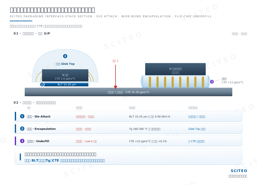
Wafer Dicing and Die Attach: The Underlying Contest of Heat, Current and Stress
The first step in semiconductor packaging is anchoring a fragile singulated die onto a leadframe or an organic substrate. It looks like a simple bonding step. It is not. That interfacial material sets electrical isolation, heat-flux conduction and mechanical survivability at once, which makes it the mechanical starting point of the whole package. In heterogeneous integration, its thickness tolerance, cure shrinkage and filler grading get amplified step by step by the dozens of chiplets and HBM stacks sitting above it.
The Silver Adhesive's Dual Electrical and Thermal Path
For power devices (MOSFET, IGBT, SiC) and logic chips that need backside grounding, the die-attach silver adhesive has to open a low-impedance electrical path and a low-impedance thermal path at the same time. SCITEO semiconductor-grade die-attach silver adhesive packs nano- and micro-scale flake silver densely into a specialty epoxy matrix. After cure it forms a continuous electronic percolation network and reaches shear strength above 10 MPa, validated against both GB/T 7124 and MIL-STD-883 Method 2019. Flake-to-flake contact density governs volume resistivity. The crosslink density of the resin backbone governs how well the interface relaxes stress under thermal cycling. The two have to be engineered together. Raising silver loading on its own pushes the system toward the brittle side, and the interface then cracks before the solder joint does.
Heat accumulation is the second problem, and it is just as fatal. If heat from a high-power die cannot get out, hot spots and thermal runaway follow. SCITEO thermal adhesives build continuous phonon pathways through an isotropic conduction lattice and multimodal particle grading, covering 4-60 W/m·K (per ASTM D5470) and draining high heat flux away from the die bottom. Conduction and thermal transport do not conflict inside one system. A single filler skeleton can carry both charge carriers and phonons, and that is the formulation thread running through SCITEO power-interface materials.
Die Insulation: Blocking Parasitic Capacitance and Leakage
Die insulating adhesive decides the reliability of mixed-signal chips, stacked memory such as 3D NAND, and RF devices. Many die backsides carry no active circuitry at all. Silicon is still a semiconductor, though, and direct contact with a biased potential readily creates parasitic capacitance or substrate leakage. That distorts high-frequency signals and flips logic states, and at the higher switching frequencies of AI accelerators and RF front ends it eats directly into signal margin. In the substrate-leakage cases we have torn down with customers, the root cause was rarely a breakdown of the insulating adhesive itself. More often, the dispense boundary did not leave enough creepage distance.
SCITEO die insulating adhesive uses a high-purity specialty epoxy system that delivers volume resistivity above 10¹⁴ Ω·cm after cure (per ASTM D257). The layer also works as a low-modulus stress buffer between rigid silicon and the copper frame, absorbing the mechanical shear introduced by their CTE mismatch and suppressing latent micro-cracking when the die heats up. Insulation and heat conduction pull against each other at this interface. The high-purity resin that suppresses leakage contributes almost nothing to thermal transport, which is why backside-grounded power dies and backside-insulated analog dies end up on two entirely different filler systems.
Dispense Rheology: Bleed-Out, BLT Excursion and Die Tilt
The process challenge centers on the dispensing stroke of a high-speed die bonder. If thixotropy is poorly engineered, the die-down compression triggers severe capillary bleed-out. Once resin climbs onto the aluminum pads on the die surface, the later wire-bond step runs into non-stick or cold joints caused by surface contamination.
Control comes down to the thixotropic index (TI) and yield stress. They keep the adhesive boundary static after compression, hold BLT inside the narrow 15-25 μm band, and prevent die tilt. Across the die-bonding lines we have cross-sectioned, the same signal keeps showing up: once BLT approaches the 25 μm ceiling, X-ray images start to reveal slight die tilt, and it remains one of the most common rework triggers in the step. On larger AI chiplets, the same tolerance magnifies into visible tilt and a thermal-resistance gradient, which is why BLT control has moved from process detail to yield gate in high-compute packaging.
Die-Attach Thermal Management for Automotive SiC/IGBT Modules
Take the SiC MOSFET power module in an EV traction inverter. Junction temperature routinely climbs past 175 °C under sustained current, and the die bottom needs an extremely low thermal-resistance path. SCITEO's 20 W/m·K thermal structural adhesive acts as the thermal bridge here: Tg 195 °C, CTE 28 ppm/°C, bond strength 22 MPa, long-term service from −45 to 280 °C. It moves heat flux from the silicon-carbide die into the ceramic-clad copper substrate. After TC500 (−40 to 125 °C) thermal cycling and HTSL 1000 h at 190 °C, shear retention holds at 95%. After 85/85 (85 °C/85% RH) humidity aging for 1000 h, it still holds 82%.
Candidates for this joint line up as a ladder. Solder gives the lowest thermal resistance, but its melting point caps the ceiling, and lead-free alloys already creep noticeably at a 175 °C junction. Conductive adhesives process gently, dispensed or printed, at the cost of limited thermal conductivity. Silver sintering pushes conduction into the hundreds of W/m·K, close to bulk silver, which suits higher heat flux, but the process window narrows sharply: it needs pressure or a higher densification temperature, and silver migration plus substrate-plating compatibility both have to be cleared. The selection point is where junction temperature, heat flux, takt time and full-life qualification intersect for that specific module. It is not a single-number comparison of thermal conductivity. Whichever route you take, verifiability weighs as much as the thermal path. AEC-Q100 and JEDEC thermal cycling decide whether the material can be written into an automotive full-life qualification, and tens of thousands of power on/off thermal shocks are the screen that eventually exposes a misjudged selection as interfacial delamination.

Post-Wire-Bond Encapsulation: Wire Sweep and Encapsulant Thermomechanics
Once the die is bonded, gold, copper or aluminum wires connect die pads to the leads. These bond wires measure only 15-30 μm across and are extremely fragile. They need local or global epoxy encapsulation for both physical and chemical defense.
Fluid Impact and Physical Control of Wire Sweep
Wire sweep is one of the most destructive failures in encapsulation. When high-viscosity liquid epoxy is dispensed over the die, the fluid wavefront exerts hydrodynamic pressure on the ultra-fine wires. Once that impact exceeds the wire yield strength, the wires bend or touch each other, causing catastrophic wire-sweep shorting.
SCITEO Glob Top encapsulant is formulated to hold adequate viscosity at room temperature and suppress spreading. On contact with a preheated substrate (around 80 °C), viscosity drops exponentially, and the material covers the wire array at low shear rate, driving fluid drag below the wire yield strength. For fine-pitch, long-span bond wires, thixotropic recovery rate matters more than initial viscosity. Recovery that is too fast builds flow resistance before the fill completes. Recovery that is too slow overflows onto adjacent pads. The longer the span and the higher the loop, the greater the moment the flow front applies to a single wire. That is why dense devices are normally dispensed starting from the side furthest from the vent, letting one front advance instead of several fronts converging on each other.
High-Tg and Reflow Protection
Packaged devices still have to survive 260 °C SMT reflow. If the encapsulant Tg is too low, the gel expands abruptly (a CTE step) and lifts bond wires off the pads, the lifted-bond failure.
SCITEO high-temperature encapsulation builds a highly crosslinked phenolic-epoxy network and raises Tg to 160-260 °C (DMA-verified). That holds dimensional stability and rigidity across the high-temperature range and gives the interconnect reliable physical anchoring. On the underfill side, SCITEO also matches a Tg 155 °C high-performance grade and a high-temperature temporary bonding adhesive for chip modules.
Choosing the Encapsulation Form: Glob Top, MUF and Local Dispensing
Different package architectures map to different encapsulation forms. Wire-bonded devices mostly use local Glob Top dispensing, where low stress and high Tg come first. Ball-grid arrays and chiplet modules lean more toward molding compound for global encapsulation. Molded underfill (MUF) merges encapsulation and bottom fill into a single step, trading some flowability for higher throughput and structural rigidity. For power modules with demanding heat paths, SCITEO offers both thermally conductive encapsulation and structural bonding, converging thermal management and mechanical protection into one material layer. The selection point is not the form itself. It is the dominant stress type the interface carries under that form.
Flip-Chip and Advanced Heterogeneous Integration: Capillary Fluid Dynamics in Underfill
In SiP, CPU/GPU and high-frequency communication modules, wire bonding can no longer satisfy I/O density and transmission speed, so flip-chip becomes mainstream. The die faces down and connects to the substrate through hundreds to thousands of micron-scale solder balls. Interconnect length is compressed to a minimum, and all of the thermo-mechanical stress concentrates on the joint array.
CTE Mismatch Between Silicon and Substrate: The Solder Joints Fatigue First
Silicon (CTE ≈ 2.6 ppm/°C) and an organic substrate (CTE ≈ 15-20 ppm/°C) expand very differently under thermal cycling. Leave it alone and all of that thermo-mechanical shear lands on the micro solder balls, which readily induces fatigue cracks. Those cracks propagate along the solder-to-copper-pad interface until the joint opens.
SCITEO underfill exists to couple stress. Capillary action fills every void beneath the die. After cure, a high-modulus crosslinked structure locks die, solder balls and substrate into one load-bearing system, converting localized solder-ball shear into global structural strain and lifting flip-chip thermal cycle life by 10-50x (evaluated per JESD22-A104). Selection therefore cannot look at Tg alone. Tg, CTE and modulus have to sit in the same coordinate frame, because only a matched triad makes stress coupling work. SCITEO low-CTE underfill converges CTE to roughly 13 ppm/°C and holds a plateaued modulus curve from −55 to 150 °C, so a modulus transition never turns into a stress spike.
Capillary Penetration and Void Entrapment: What the Washburn Model Explains
Once micro-bump pitch drops into the hundred-micron range and the gap goes below 50 μm, the adhesive moves purely on surface-tension-driven capillary flow. The Washburn model sets the quantitative frame: fill time scales roughly with the square of flow distance and with viscosity, and inversely with gap height, surface tension and the cosine of the contact angle. That one relation explains two counterintuitive field observations. Double the die edge and fill time has to be re-estimated on a fourfold basis. Squeeze the gap from 50 μm to 20 μm, and lowering viscosity alone usually will not save you; filler grading and wetting have to move with it.
Voids are the first-order failure on this path. An ill-chosen dispense path (I-type or L-type, for example) or a mismatched surface energy makes the flow front uneven and entrains micro-bubbles at the die center or bump edges. Under later heating those bubbles expand, squeeze adjacent solder balls and shift the local stress distribution, which ends in shorts or interfacial delamination. SCITEO underfill uses specialty surfactants to tune surface tension and keeps a smooth advancing front through the bump array for dense, bubble-free fill. In the underfill void cases we have reviewed, the root cause landed on the dispense path far more often than on the formulation. The narrower the bump pitch, the more an I-type path traps air at the center confluence, and switching to an L-type or U-type path is often immediately effective. Large AI chiplets also need vacuum-assisted cure matched to the substrate preheat profile before void rate can be held below 0.1%. Watch the ratio of minimum gap to maximum filler particle size too. Field experience puts the floor at three to five times, and below that, filler packing in a narrow gap starts manufacturing voids on its own.
CoWoS and HBM4: Stress Redistributes Across a Larger Area
In CoWoS-class advanced packaging for AI training and inference servers, several compute chiplets and high-bandwidth memory (HBM) stacks sit side by side on a silicon interposer, and die-to-interposer CTE mismatch is amplified across hundreds of thousands of micro-bumps. HBM4 widens the interface to 2048-bit and moves the base die to a 4 nm logic process. Shipping parts run from the JEDEC baseline of 8 Gbps up to 11.7 Gbps, with 13 Gbps at the top end, putting per-stack bandwidth in the 3.3 TB/s range. Through-silicon vias and bottom micro-bumps number in the tens of thousands per stack, and memory-to-logic thermo-mechanical coupling is tighter than in any previous generation.
Power pushes on the same layer. Single-package power has moved into the kilowatt class, and foundry roadmaps keep pointing higher, so the cooling architecture has shifted to liquid. Heat has to be spread inside the package rather than chased by the cold plate.
SCITEO low-CTE underfill (roughly 13 ppm/°C) serves as the structural adhesive here, converting localized shear into tolerable global strain through full-temperature Tg/CTE/modulus matching. For high-compute scenarios that also need active heat removal, thermally conductive underfill upgrades bottom fill from passive filling to active heat conduction and backstops long-term thermal stability for kilowatt-class chips. Under 800 V HVDC rack power and direct-to-chip liquid cooling, the underfill layer also sees steeper temperature gradients, which raises the demand on its damping capacity in the low-modulus regime.
Panel-Level Packaging and Glass Substrates: The Interface Chemistry Changes
Package scaling is rewriting the boundary conditions for underfill and die attach. Once a single package carries multiple compute chiplets plus a dozen or more HBM4 stacks, the interface count multiplies, the stress budget handed to each layer thins out, and warpage stops being a secondary concern. Carrier form pushes the same constraint one step further. Area utilization on a round wafer typically lands around 60% for large packages, while panel-level packaging (PLP) on a rectangular panel lifts it toward 90%, at the cost of CTE mismatch across a longer span and more stacked RDL layers.
Glass-core substrates and glass interposers are the other route in the same direction. They replace the organic core with glass whose CTE can be tuned, improving warpage control and high-frequency dielectric loss at once, and through-glass vias (TGV) take over part of the silicon vias. The interface chemistry changes wholesale, though. Glass is smooth and bonds weakly to metal, so the coupling system has to be redesigned and cure shrinkage re-tuned against low-modulus buffering, or the interface fails before the solder joint does. Brittleness adds a second cost: micro-cracks opened during drilling and metallization propagate along the interface, and the yield loss still lands on the interface line item. Large-area thermal lamination in panel-level packaging then requires dense fill at low pressure, which is why SCITEO materials for panel-level packaging and glass substrates are developed against four constraints at once: low-modulus buffering, low shrinkage, low outgassing and interfacial coupling.
Dispensing: The Other Half of the Problem, Beyond Adhesive Data Sheets
In customer fabs we have seen the same situation too many times. The formulation passes every spec, yet yield stalls at the dispense step. In the packaging chain, dispensing stability directly determines final package yield, and it frequently exceeds the single-parameter boundary of the adhesive itself.
Thixotropic Collapse and Time Dependence in Non-Newtonian Fluids
Semiconductor adhesives are highly filled non-Newtonian fluids. During extended continuous dispensing, filler settling or small ambient-temperature drift causes viscosity drift. That demands real-time closed-loop weight calibration and constant-temperature valve control, and the formulation itself needs very long pot life and rheological stability. For highly filled multimodal systems, filler settling velocity and matrix yield stress have to be calibrated together, otherwise one part number yields a different BLT at the start and end of a shift.
High-Frequency Shear and Satellite Droplets in Piezo Jet Valves
To meet high UPH (units per hour), modern packaging widely adopts non-contact piezoelectric jet dispensing. The needle strikes the fluid at hundreds of hertz and generates extreme shear rates. When the polymer chain segments do not have enough elasticity, the droplet-breakoff moment throws off microscopic satellite spatter that contaminates exposed sensors or metal pads. The fix sits at the synthesis level: narrow the molecular-weight distribution strictly and hold elastic response time within one tenth of the jetting period. Once single-drop volume converges into the nanoliter range and jetting frequency climbs into the kilohertz band, transient rheological response and nozzle material jointly govern shot-to-shot mass stability. Zirconia-toughened alumina (ZTA) ceramic nozzles are the execution-end answer, specified for the wear resistance and flow-path consistency that highly filled adhesives demand.
Packaging Adhesive Selection Quick Reference
The failure physics above compress into a process-step-to-selection-window map a review meeting can work straight through:
| Process Step | Dominant Failure Mode | Core Process Window | SCITEO Product Direction |
|---|---|---|---|
| Power-device die attach (SiC/IGBT) | Power-cycling interfacial shear fatigue | High conductivity, low CTE, high Tg | 20 W/m·K thermal structural adhesive, conductive silver adhesive |
| Logic and memory die attach | Parasitic capacitance and substrate leakage | Volume resistivity >10¹⁴ Ω·cm | Die insulating adhesive |
| Wire-bond encapsulation | Wire sweep and pad lift-off | Thixotropic index, Tg 160-260 °C | Glob Top encapsulant |
| Flip-chip underfill | Solder-joint fatigue and low-k tearing | Tg/CTE/modulus matching | 13 ppm/°C low-CTE underfill |
| Large CoWoS and HBM4 stacks | Warpage and micro-voids | Stable capillary front, void rate <0.1% | Low-stress thermally conductive underfill |
| Panel-level packaging and glass substrates | Large-area warpage and TGV interface stress | Low-modulus buffer, low shrinkage, low outgassing | Panel-level packaging material set |
Thermal Resistance, Shrinkage and Modulus: No Single-Parameter Optimum
From the basic leadframe to 3D heterogeneous integration, semiconductor packaging is a continuing contest with thermodynamics and fluid mechanics at nano- and micro-scales. Pushing one parameter to its limit is not hard. Keeping it from fighting the other two inside one formulation is.
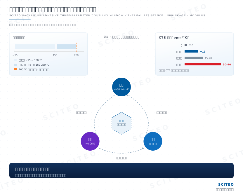
SCITEO Advanced Materials has built a full chain through deep epoxy synthesis and modification. Its product direction spans electrical lockdown at die insulation, rheological control against wire sweep, and deep capillary penetration in flip-chip. The thermal-bridge design of an automotive power module and the stress redistribution of an AI compute chip come down to the same class of question at the review table: how thermal resistance, shrinkage and modulus trade off together, not which isolated number is higher.
Look one step further out and the next packaging forms are already taking shape. HBM4 keeps scaling through stack count and the base-die logic process. Co-packaged optics (CPO) puts the optical engine and the switch ASIC on one substrate. Glass-core substrates and panel-level packaging are moving through commercial sampling and pilot-line qualification. There will only be more interfaces, and every layer leaves less margin. That leaves the ten-micron transition zone between glass, copper and polymer as the place where a package still gets decided.
This article is SCITEO Advanced Materials original technical content; unauthorized reproduction is prohibited.
Appendix: Process & Engineering Adhesive FAQ Index
Why must die-attach BLT stay under 25 μm, and why is die tilt never acceptable?
BLT and die tilt are two independent constraints that happen to land on the same parameter. A thicker bond line means higher thermal resistance, so heat from the die core cannot get down efficiently and junction temperature walks into the reliability limit. That is why 15-25 μm is the window calibrated repeatedly between thermal resistance and fill completeness. Thinner is not automatically better either. As BLT shrinks, the ratio of filler particle size to gap height tightens, edge fill falls short and voids appear, so thin and dense have to hold at the same time. Die tilt is a separate line of failure. In multi-chip stacks and actively aligned optical coupling, micron-level tilt accumulates along Z and drags the wire-bond loop height of upper dies and the optical coupling position with it. When cross-sectioning or X-ray imaging picks up tilt, review dispense volume and placement force before you touch the formulation.
How does an encapsulant avoid leaving residual tensile stress on fragile gold wires during cure?
The key is driving cure shrinkage to its engineering floor. Thermoset crosslinking always involves volume shrinkage, and when shrinkage runs high the cured encapsulant keeps the internal bond wires under tension. Add one thermal cycle on top and ball bonds and wedge bonds become the first fatigue sites. SCITEO's organic-inorganic hybrid prepolymer design holds cure linear shrinkage below 0.06% while carrying Tg to 160-260 °C, so the encapsulant also holds dimensional stability through a 260 °C reflow peak. Shrinkage and Tg have to be read together. Press shrinkage down while ignoring heat resistance, and a single reflow excursion still lifts a bond wire off its pad.
Is a higher Tg always better for flip-chip underfill?
No. Tg has to line up with the thermo-mechanical behavior of the die, solder balls and substrate across the full temperature range. A high Tg means modulus is retained at elevated temperature, but if CTE has not been matched to go with it, an over-rigid underfill cannot absorb thermal strain during an extreme swing like reflow, and that stress is pushed down into the fragile low-k dielectric as the white bump defect. The process window in advanced packaging therefore sits on the linkage between Tg, CTE and modulus. Mismatch CTE against silicon and the interface cracks first. Match CTE but under-run Tg, and a modulus transition inside the working range redistributes the load path, turning the solder joint from a protected element into a new load-bearing one.
Flip-chip underfill keeps entraining micro-bubbles. How should the dispense path and surface tension be tuned?
Micro-bubbles trace back to capillary flow-front instability. Once bump pitch narrows and the gap drops below 50 μm, the adhesive is driven almost entirely by surface tension, and the advancing front is highly sensitive to gap height, viscosity and contact angle. Mismatch the surface energy or choose the wrong path, and several flow fronts converge at the die center, sealing the vent channels early and trapping air between solder balls. Two actions pay off fastest on the line. Use specialty surfactants to move the contact angle into a stable window so the front advances flat. Replace an I-type path with an L-type or U-type path to stay away from the center confluence. Large AI chiplets also need vacuum-assisted cure matched to the substrate preheat profile before void rate can be held below 0.1%.
For automotive SiC/IGBT power-module die attach, why does high thermal conductivity plus low shrinkage come before chasing a high Tg?
Because the dominant failure is thermal fatigue, not high-temperature softening. Wide-bandgap devices routinely run junction temperatures above 175 °C, and the heat flux out of the junction needs a low-resistance path into the ceramic-clad copper substrate, where thermal conductivity and bond-line thickness together set the thermal resistance. Cure shrinkage and CTE mismatch meanwhile keep accumulating shear stress at the die bottom and bring interfacial delamination forward. Selection has to satisfy high conduction, low shrinkage and adequate Tg at the same time, then close the loop with AEC-Q100 and JEDEC thermal cycling for full-life validation. Miss any one of the three and the module returns to that same delamination path after tens of thousands of power on/off thermal shocks.
What new problems do HBM4 stacks, large-format CoWoS packaging and glass substrates hand to packaging adhesives?
These three architectures tighten three constraints inside the same window. HBM4 widens the interface to 2048-bit and moves the base die to a 4 nm logic process, and shipping parts already run from the JEDEC baseline of 8 Gbps to 11.7 Gbps, putting per-stack bandwidth in the 3.3 TB/s range. More than 20,000 through-silicon vias and 16,000 bottom micro-bumps per stack couple memory and logic chiplets more tightly than before, so underfill has to combine low CTE with low-modulus damping inside thinner gaps. CoWoS-class packages keep scaling in area, and once area grows, warpage stops being a secondary concern and becomes a first-order constraint, so underfill and die-attach layers have to hold both void rate and residual stress across a large area. Glass-core substrates change the interface chemistry outright. Glass is smooth and bonds weakly to metal, and metallization inside sub-10 μm through-glass vias plus nanometer-level flatness across large panels are still being worked through, so the material has to balance interfacial coupling, low shrinkage and low outgassing.