High-Density PCBA Encapsulant Selection: SiP, Underfill and Piezo Jet Dispensing Interface Failure Mechanisms
SCITEO interface material systems for AI compute boards, EN 50155 rail transit electronics and MMC valve control boards: ultra-low-shrinkage potting, low-CTE underfill, high-thermal structural bonding and irreversible anti-tamper encapsulation
Abstract
Failure in high-density PCBA has moved out of the solder joint and into the interface between component and board. System-in-package, chiplet heterogeneous integration and kilowatt-class compute boards push interconnect density, heat flux and supply current upward together, and the problems soldering metallurgy cannot solve end up resting on a layer of adhesive a few tens of micrometers thick. CTE mismatch, drop impact and ion migration under humid bias each find the weakest exit along that interface, and these exits do not share a fix: CTE mismatch goes to low-CTE underfill, drop impact and board bending to high-modulus edge bonding, and humid bias plus high-voltage surface tracking to a high-CTI, low-mobile-ion potting system. SCITEO works backward from the application side: establish how the board fails in service first, then decide how low the shrinkage has to be, how wide the modulus window needs to be, and how strict an ionic cleanliness budget the adhesive can carry. The article runs from board-level limits through process fit and validation data to selection criteria.
Core Parameter Comparison
The table below lists key metrics for SCITEO PCBA interface materials against industry-typical electronic adhesives:
| Parameter | SCITEO Solution | Industry Typical | Test Standard |
|---|---|---|---|
| Cure volume shrinkage | <0.06% | 1-3% | ISO 2577 (derived from linear shrinkage) |
| Extreme operating temperature range | −65 °C to +280 °C | −40 °C to +125 °C | MIL-STD-810G |
| Thermal conductivity range | 2.0-60 W/m·K | 0.5-1.5 W/m·K | ASTM D5470 |
| Structural shear strength | 20-32 MPa | 2-5 MPa | GB/T 7124 |
| CTE (low-CTE grade) | 13-30 ppm/°C | 50-80 ppm/°C | TMA |
| Volume resistivity | >10¹⁴ Ω·cm | 10¹²-10¹³ Ω·cm | ASTM D257 |
| Piezo jet frequency compatibility | >200 Hz | <100 Hz | n/a |
| Reflow endurance at 260 °C | 3 or more passes without damage | Cracks after a single pass | J-STD-020 |
| Extractable ion content (Na⁺/Cl⁻) | ≤10 ppm | 30-100 ppm | IC ion chromatography |
Shrinkage and modulus decide how much stress collects at the interface and where it travels, thermal conductivity sets the cross-section heat can leave through, ion content sets insulation life under humid bias, and jetting compatibility decides whether a grade can run on a high-tempo line at all. The variables constrain one another, so raising any single one does not buy overall reliability.
Physical Limits of High-Density PCBA
Once a board reaches 40 μm-class line and space, more than 20 layers and tens of thousands of solder joints, the tolerance left for materials is a few micrometers and a few degrees Celsius. 01005 and 008004 passives, BGA and CSP packages on sub-0.3 mm pitch, and chip-scale packages under 0.4 mm thick share one substrate, and any local interface mismatch amplifies along the board, copper and resin load paths into a whole-board failure. System-in-package pushes the same problem into a tighter space: dies, passives and shield cans are compressed into a single module, package-on-package stacks and embedded components carry the interface from the board surface into the package itself, the gap left for capillary underfill flow is often in the 50 μm class, and the module cavity is both dark to UV and hard to fill completely.
CTE Mismatch and Solder Joint Fatigue
Silicon sits near 2.6 ppm/°C, FR4 glass-reinforced resin at 15-18 ppm/°C, ceramic substrates at 6-8 ppm/°C, and aluminium or copper heat spreaders at 17-23 ppm/°C. Reflow cooling and in-service thermal cycling make these materials contract at different rates, and the accumulated dimensional difference lands on micron-scale solder balls and copper pillars as repeated shear strain. Lead-free SAC alloys reflow at 245-260 °C, intermetallic layers keep growing at the joint, Cu₆Sn₅ and Cu₃Sn turn progressively more brittle with thickness, and cracks usually initiate there and propagate toward the joint root. Under temperature cycling to JEDEC JESD22-A104, failures tend to appear first at the package edge, in the same positions the warpage pattern predicts. Underfill criteria therefore have to be read as a pair: CTE alone misses modulus collapse at peak temperature, and Tg alone misses how quickly interfacial shear accumulates.
Mechanical Shock, Board Bend and Pad Cratering
Inertial loads from drops, shocks and sustained vibration carry stress from the component body into the joint between pad and resin. Where local board stiffness is low, or where heavy parts such as large electrolytic capacitors, inductors, transformers and metal shields lack restraint, the pad lifts together with the resin beneath it. The awkward part is timing: it does not always appear after reflow, and sometimes only surfaces once thermal cycling and vibration combine. Layout changes and added support points relieve part of it, and the more common remedy is a low-CTE, high-modulus underfill or edge-bond adhesive that locks relative displacement at the joint and lets impact energy dissipate in a tougher resin. Modulus and Tg have to be reviewed alongside it, or the stress simply relocates from the joint into the component body.
Humid Bias and Electrochemical Migration
Below 0.3 mm pitch, flux residue, polar groups inside the laminate and adsorbed moisture link up into local electrolyte paths under bias. Mobile sodium and chloride ions migrate along the field, metal dendrites grow between adjacent pads, and insulation resistance drops off a cliff. Between glass bundles and resin, conductive anodic filament growth can take hold as well, with a channel buried inside the laminate where visual inspection and routine insulation tests are unlikely to find it. The meaningful criteria are therefore resistance retention after humid-bias aging and extractable ion content, not initial insulation resistance. SCITEO holds extractable ions below 10 ppm and re-verifies volume resistivity before and after moisture uptake per ASTM D257.
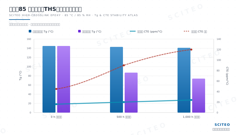
Moisture damage does not travel only one route. Water molecules entering the crosslinked network act as a plasticizer, pulling glass transition temperature down and pushing the coefficient of thermal expansion up, so the material crosses its new Tg more easily during a later reflow pass or a hot summer at full load, and the resulting modulus collapse and extra expansion reach the solder joint as shear stress. Accelerated humid-bias screening normally runs either 85 °C/85% RH (THB) or HAST; the chart below takes the THB path over 1000 hours. A conventional epoxy falls to roughly 74 °C Tg over 1,000 hours with CTE climbing into the 120 ppm/°C range, while the SCITEO epoxy holds its Tg and lets CTE rise only from 16 to 24 ppm/°C.
SMT Assembly: Thermal History, Flux Residue and Stencil-Free Jetting
The assembly line is the first thermal process a board goes through, and it is that history the interface material has to survive. Of the four main steps — paste printing, placement, reflow and inspection — the first two hand over geometric tolerance, while the last two leave the adhesive with a thermal and chemical bill: the lead-free liquidus window runs past 217 °C, double-sided assembly and rework stack three or more thermal passes onto the same board, and flux activation leaves a residue layer on pads and laminate. Thermal history sets how much modulus margin the components and the adhesive still have; the residue decides whether underfill, edge bonding and conformal coating can build stable wetting on top of it.
Two process shifts are rewriting that bill from opposite ends. One is the stencil-free route: piezo-actuated jet valves deposit paste straight onto pads from the Gerber data, with minimum deposits down to 125-200 μm, skipping aperture design and squeegee transfer, so deep-cavity packages, flexible substrates and high-mix low-volume lines are no longer tied to stencil cost and inventory. The physics is the same tappet shear plus thixotropic recovery covered later for dispensing, with solder swapped in for adhesive. The other is low-temperature soldering: eutectic Sn42Bi58 melts at 138 °C and reflows at a peak of 165-190 °C, more than 70 °C below SAC305, which relieves the warpage load on heat-sensitive components and large thin boards. The cost sits in the microstructure — bismuth-rich grain boundaries are inherently brittle, Bi segregates into a brittle layer at the Cu₆Sn₅ interface, drop and shock performance falls well short of SAC, and the structure coarsens even at a steady 80-100 °C. Which boards it belongs on is a duty-cycle decision, not a peak-temperature one.
Residue compounds the problem, and the pressure lands on the adhesive. Nitrogen reflow holds furnace oxygen in the 1000 ppm band, which suppresses oxidation and solder balls but does nothing about the residue layer: no-clean chemistry removes the washing step and leaves a thin film of activators and film-forming resin that shifts pad surface energy, so underfill tends to spread with an uneven flow front and interfacial voids, while residual active ions feed electrochemical migration under humid bias. Once low-temperature soldering pulls the peak down, the cure window opens with it. SCITEO supplies low-temperature-cure grades of underfill and edge-bond adhesive matched to the cadence of low-temperature alloys, and writes contact-angle tolerance and a ≤10 ppm mobile-ion budget into the delivery spec, so an unwashed board still builds stable wetting and insulation margin.
Two Kinds of Pressure from the Application Side
Two directions amplify board-level limits at once. The first is compute and RF: kilowatt-class accelerators, 224G SerDes switch boards, 800G and 1.6T optical modules and near-packaged-optics supernodes raise board power, heat flux and signal rate together, so any layer of interfacial thermal resistance converts into temperature rise and link margin loss. The second is long life, wide temperature and high voltage: rail transit electronics carry design lives measured in decades, and MMC valve halls run year-round at high temperature inside an ultra-high-voltage field. Both demand materials that barely age across the whole service period. Specifications can only be derived backward from those failure modes, and a general-purpose consumer-electronics formulation will not cover them.
Piezo Jet Dispensing: Rheology and Line Tempo Under One Constraint
What a datasheet promises is only half the capability; the other half is whether the chemistry can actually run on a customer's line. Once interconnect density is near its limit, material and equipment have to be engineered as one coupled system, because optimizing either side alone gets cancelled out in yield.
From Contact Needles to Non-Contact Jetting
Contact pneumatic needle dispensing carries inherent process limits. The needle has to descend close to the board to transfer adhesive, so Z-axis travel conflicts spatially with components already placed, and a small error in lift height either damages a die or crushes fine traces. Volume transfer depends on surface tension, which makes repeatability a function of viscosity and needle diameter drift. Non-contact piezo jet valves change the logic: a piezoelectric actuator drives a tappet at hundreds of hertz, the adhesive is sheared off and accelerated at the nozzle, and discrete droplets in the microliter to nanoliter range fly out with placement set by the motion platform. A millimeter-scale standoff between nozzle and board means dispensing onto complex three-dimensional surfaces, into cavities and along the edges of dense components no longer depends on mechanical clearance. Leading consumer-electronics and compute-chip SMT lines adopt this approach, and the yardstick for process capability moves with it, settling on how accurately the droplet lands.
High-Shear Thinning and Thixotropic Recovery
Fitting a piezo jet valve is not a matter of lowering viscosity. Too thin, and the droplet creeps across the board and attacks neighbouring pads; too thick, and the tappet travel cannot complete shear thinning, which produces short shots and broken streams. SCITEO uses precisely graded polymeric thixotropes to give single-component adhesives a controlled non-Newtonian profile: viscosity falls sharply under the extreme shear rate at the tappet so ejection is clean with no satellite droplets or stringing, and the structure rebuilds within seconds after the droplet contacts the substrate so the dot holds its profile instead of collapsing. Both response speeds have to land in window, which is why one formulation can behave very differently on two machines.
Stencil Printing and Full-Board Coating Compatibility
Not every step suits dot-by-dot jetting. For high-volume, full-board coating of heat-cure systems, and for reinforcement or sealing steps that need tight control of adhesive thickness, stencil printing is the more efficient route. SCITEO developed a high thixotropic index system for these duty cycles: it fills apertures cleanly under squeegee shear, then builds structure immediately after release, without stringing or edge slumping, and runs on standard SMT printing equipment at line tempo. Because one material platform covers both jetting and printing, process engineers can switch patterning methods during a capacity ramp without re-qualifying an entirely separate flow.
Air Entrapment, Nozzle Wear and Closed-Loop Parameters
Jetting is extremely sensitive to entrained air; a single micron-scale bubble is enough to cause a short shot or a stray droplet, which makes vacuum centrifugal de-aeration and incoming cleanliness non-negotiable. Nozzle and tappet wear matter just as much, because thermal and conductive adhesives carry hard fillers such as alumina, boron nitride and silver flake, and sustained impact changes the nozzle bore and the striking face, which in turn changes droplet volume. The usual countermeasures are sintered-diamond or ceramic-lined nozzles together with a narrow syringe temperature window, since most epoxy systems lose 15% to 25% of their viscosity for every 10 °C rise, and dispensed volume drifts with it. SCITEO ships viscosity-versus-temperature and thixotropic-recovery curves with the material so the line can close the loop across temperature, pressure and tappet stroke, and hold dispensed volume inside the process window.
Engineering Validation Data for SCITEO PCBA Interface Materials
Duty cycles differ widely between the second half of PCBA manufacturing and end-of-life service, so SCITEO application engineering configures materials by failure mode and anchors each specification to a test method the customer can reproduce.
Ultra-Low Shrinkage and Wide-Temperature Potting
This family targets the rear section of aerospace connectors, specialty power modules and assemblies that need full-depth protection. In sampling, the first number reviewed is cure shrinkage, because the residual stress it creates usually shows up as a cracked ceramic capacitor or a displaced pin.
The base epoxy potting system covers an operating range of −65 °C to +280 °C, meeting and exceeding the MIL-STD-810G low-temperature requirement. Derived from ISO 2577 linear shrinkage, volume shrinkage is held below 0.06%, so cure exerts almost no physical drag on internal fine pins, and the cured body reaches Shore D 85 or higher, which supplies structural support while retaining toughness margin. On the thermal side, the system passes repeated 260 °C reflow per J-STD-020 without damage, leaving process margin for double-sided assembly and rework. For chip-module packaging that needs high-temperature temporary fixation, SCITEO supplies reflow-resistant, chemically resistant temporary bonding and debonding adhesives that release cleanly in both dry and wet processes.
Extreme Thermal Management and High-Strength Bonding
In drone ESCs, high-power IGBT modules and base-station RF power amplifiers, trapped heat is the direct cause of parameter drift and eventual thermal runaway. Once board-level heat flux reaches tens of watts per square centimeter, the adhesive between device and heat spreader becomes a segment of the thermal resistance network, and it has to be selected on thermal resistance rather than on coverage area.
SCITEO thermal systems span 2.0 W/m·K to 60 W/m·K, and on request interfacial thermal resistance is re-measured per ASTM D5470 at the target pressure and bond-line thickness so a single-point number cannot mislead a design. Even at high filler loading the system holds 20 MPa to 32 MPa destructive shear strength per GB/T 7124, so it serves as both thermal medium and structural joint, and the interface does not delaminate after repeated reflow and thermal cycling. Die attach is the next interface on the same heat path: where the power device also needs electrical interconnection, SCITEO conductive silver adhesives trade thermal conductivity against volume resistivity and keep silver migration and interfacial voids inside the life budget. On high-voltage platforms the potting body must insulate as well: the corresponding grades reach a comparative tracking index above 600 V per IEC 60112 and maintain dielectric strength above 18 kV/mm per IEC 60243-1, allowing conduction and insulation to coexist in one volume.
Pin Reinforcement and Low-CTE Protection
For ultra-fine-pitch pins and heavy components, SCITEO low-CTE protective adhesives measure below 30 ppm/°C by TMA, with the lowest grades reaching 13 ppm/°C toward silicon and ceramic. The high-modulus network that forms on cure locks relative displacement at the joint interface and moves drop and vibration energy from the brittle solder into the tougher resin matrix, which lifts drop and vibration performance and reduces cold joints and pin fracture. Grades that run a capillary underfill (CUF) path instead hold a continuous flow front through 50 μm-class gaps, using surface energy and filler grading to bring fill time inside the line tempo while keeping void area fraction below the acceptance limit. Underfill Tg is held in the 100-155 °C window by DMA, balancing modulus at peak process temperature against compliance at room temperature. Cratered pads account for a substantial share of the failed boards seen in drop testing, and underfill CTE matching and modulus window are the first line of defence against that mode. Reviewing CTE, Tg, cure shrinkage and extractable ion content on one table keeps a fix for one failure mode from creating another.
Irreversible Anti-Tamper and Hardware-Level Information Protection
In high-end control boards, classified communication modules and algorithm-centric ICs, preventing reverse engineering through optical microscopy, layer-by-layer polishing or chemical etching is a core security requirement. Once firmware encryption and secure boot became standard, physical accessibility turned into the easiest way in.
SCITEO anti-tamper encapsulants cure into a dense, hard and opaque polymer envelope with strong chemical inertness, resisting isopropanol, acetone, toluene and other standard industrial solvents. Any attempt to remove the layer by melting or chemical stripping destroys the traces and dies inside it first, so the information yield of reverse engineering goes to zero physically. With extractable ion content held at or below 10 ppm, the envelope does not become a new electrochemical migration source, so confidentiality measures and long-term reliability no longer work against each other. Where both confidentiality and serviceability are required, SCITEO recommends splitting the design by protection tier: irreversible potting over the algorithm core, and locally removable reinforcement around the interface region.
UV-Thermal Dual Cure and Shadow-Zone Crosslinking
FPC stiffening and opaque shield-can fixation have long been limited by shadow zones. A purely UV-curable system stays liquid where light never reaches, which provides no structural strength and risks bleeding into later process steps.
The SCITEO photo-thermal interpenetrating network system chains the two cure mechanisms onto one process flow: exposed areas fixture within seconds under UV to meet high-tempo line positioning, while the liquid trapped beneath components triggers a latent thermal cure in the subsequent mid-low-temperature tunnel oven and builds a dense crosslinked network. The design balances tempo against deep-cure reliability, and it brings the final crosslink density of shadow zones and lit areas close together, which reduces stress concentration points created by an uneven degree of cure.
Application Mapping: From Compute Boards to Valve Control Boards
The four scenarios below place very different combinations of demands on board-level interface materials, and each has to be solved on its own terms.
AI Compute and Data Center Switch Boards
Compute boards combine sustained high load, locally extreme heat flux and very high signal rates. Kilowatt-class accelerators push supply current into the hundreds of amperes, so the interfaces on multilayer copper bars and heavy-copper planes have to conduct, transfer heat and hold structure at the same time. 224G SerDes links with 800G and 1.6T optical modules require a stable dielectric constant and low loss across a wide temperature range, and SCITEO grades for RF and optical modules hold dielectric constant (Dk) between 3.2 and 3.8 with loss tangent (Df) below 0.01 at 1 MHz while restricting cure shrinkage and extractable ions, which protects coupling position and insertion-loss margin. In near-packaged and co-packaged optics the optical engine shares a package with the switch die, and sub-micron alignment tolerance turns cure shrinkage into a first-order yield variable, which is why low-shrinkage, low-modulus stress-buffering formulations are standard on those boards.
Rail Transit Traction and Onboard Electronics
Rail transit electronics are mounted as cabinets or subracks on the car body, on bogies, or even on the axle. EN 50155 grades temperature class, supply interruption and rapid temperature variation for this equipment, shock and vibration are handled by IEC 61373 across body-mounted, bogie-mounted and axle-mounted categories, and enclosures plus cabling must satisfy the fire and smoke requirements of EN 45545-2. Axle-mounted equipment takes the highest loads and body-mounted equipment the mildest, but every category faces a design life measured in decades with essentially no downtime window.
At board level the difficulty concentrates in three places. Rapid temperature swings as a train passes through tunnels condense moisture on cabinet walls, and that water film under bias readily pushes fine-pitch pads toward electrochemical migration. Boards near traction and auxiliary converters live with vibration superimposed on harmonic current, so pads and pins around mounting points are usually the first to fatigue. Surges from contactors, relays and large inductors, plus a wide supply-voltage range, demand generous insulation and withstand margins. The usual material set combines wide-temperature underfill to lock the joints, corner bonding to absorb board-level bending, and conformal coating qualified under the IPC-CC-830 framework as a moisture and salt-spray barrier; the corresponding SCITEO grades retain up to 95% shear strength after 1000 thermal cycles between −40 °C and +125 °C. EN 50155 class OT6 sets operating temperature at −40 °C to +85 °C, and PCB self-heating typically adds another ten-plus degrees Celsius inside the enclosure, so that stack-up has to be included in selection, or room-temperature data stops holding once the board is inside the cabinet.
HVDC Flexible Transmission and Valve Control Boards
Flexible HVDC transmission couples the AC and DC sides through a modular multilevel converter, and a 1 to 2 GW link typically needs two thousand to four thousand submodules working in series and parallel. The converter valve is that stack of submodules, and the valve control system handles firing control, fault protection and condition monitoring, which makes it the core control function of the converter station. On older DC projects, replacing whole valve control cubicles and swapping trigger check-back boards in bulk during domestic-equipment retrofits has become a routine cadence, and boards are specified to be replaceable and individually isolated while the link stays energised.
The hall is not a comfortable place for a board. The valve tower sits on a very high potential platform, and the control power supply is separated from the low-voltage ground side by mains-frequency withstand insulation rated above 100 kVAC, with some UHV projects asking for more. The extreme voltage slew rates from IGBT and IGCT switching couple into common-mode disturbance in the tens of kilovolts per microsecond range, and where the insulation contains a void or a delamination, partial discharge starts there; project acceptance commonly caps partial discharge at the 10 pC level at 1.1 times rated voltage, measured per IEC 60270. Offshore converter platforms add heavy salt spray, high humidity and fungal growth on top. Potting carries both the insulation and the structural role here: a high-CTI formulation closes down surface tracking paths, low-shrinkage cure avoids introducing stress cracks in thin-walled cavities, and low-outgassing grades keep volatiles from depositing inside a sealed valve hall. With a 30-year design life and mean time between failures in the 5×10⁵ h class, the ageing curve has to be worked out during selection rather than patched later through inspection rounds once the link is in service.
Avionics Flight Control, Inertial Navigation and High-Density Micro-Assembly
Avionics defines reliability very differently from consumer electronics: sustained vibration, wide thermal cycling, long service life and no repair opportunity all hold at the same time, and a single interface failure can map directly to a failed mission. Fly-by-wire flight control computers, inertial navigation units, laser and fiber-optic gyroscopes, MEMS gyroscopes and star trackers are built with high-density micro-assembly that compresses dies, sensors and circuitry into very small volumes, often leaving only a few tenths of a millimeter for material. In these structures the potting compound carries four roles at once: thermal conduction, insulation, structural fixation and vibration damping. The requirements on cure shrinkage, CTE matching and outgassing all sit above commercial-industrial grade. SCITEO work across low-stress buffering, low shrinkage and wide temperature range is built around the process window of exactly this class of high-reliability assembly.
Interface Material Selection Quick Reference
The table below compresses the failure mechanisms above into executable selection criteria for process engineers to check during review:
| Process Segment | Typical Failure Mode | Key Criteria | SCITEO Direction |
|---|---|---|---|
| SMT assembly and reflow | Underfill voids from flux residue, brittle fracture in low-temperature alloys | Surface-energy tolerance, ≤10 ppm mobile ions, low-temperature cure window | Low-temperature-cure underfill and edge-bond adhesives |
| Pin reinforcement and corner bonding | Pad cratering and pin fracture under drop impact | CTE 13-30 ppm/°C, high modulus, Tg 100-155 °C | Low-CTE underfill and edge-bond adhesives |
| Chip underfill | Voids from insufficient capillary flow, interfacial delamination under thermal cycling | Capillary flow, void area fraction, extractable ions ≤10 ppm | Underfill encapsulants |
| SiP modules and die stacks | Underfill voids inside the module cavity, delamination at PoP interfaces | Capillary flow through 50 μm-class gaps, low shrinkage, low outgassing | Module underfill and dam-and-fill encapsulants |
| Power device to heat spreader bonding | Interfacial thermal resistance drift, thermal-layer pump-out | 2.0-60 W/m·K, 20-32 MPa shear, re-verified interfacial resistance | High-thermal structural bonding adhesives |
| Aerospace connector and power module potting | Cure shrinkage stress cracking MLCCs and glass-bodied devices | Volume shrinkage <0.06%, −65~+280 °C | Ultra-low-shrinkage wide-temperature potting |
| FPC stiffening and shield-can fixation | Incomplete shadow-zone cure, tacky or bleeding interface | UV fixture plus latent mid-low-temperature thermal cure | Photo-thermal dual-cure adhesives |
| Classified boards and algorithm modules | Optical microscopy and chemical-etch reverse engineering | Chemical inertness, irreversible stripping, ≤10 ppm ions | Anti-tamper encapsulants |
| Rail transit onboard boards | Long-term vibration fatigue, electrochemical migration under condensation and salt spray | EN 50155 temperature class, IEC 61373 vibration, EN 45545-2 fire performance | Wide-temperature underfill and conformal coating |
| Converter valve hall and offshore platform boards | Partial discharge inception, wide-temperature ageing, fungal attack | CTI ≥600 V, partial discharge ≤10 pC, low-outgassing potting | High-insulation wide-temperature potting |
Conclusion
Board-level options have narrowed considerably by now. Solder alloys, laminate systems and stack-ups were fixed by standards long ago, and much of the remaining freedom sits in the adhesive layers that used to be treated as consumables. Once cure shrinkage, the modulus window and ionic cleanliness are pinned down against the duty cycle, board-level reliability moves from a problem discovered at final test to one that can be calculated during design. SCITEO Advanced Materials works from first-principles synthesis data and hands formulation, process window and validation data to the PCBA manufacturing floor as one package.
This article is SCITEO Advanced Materials original technical content; unauthorized reproduction is prohibited.
Appendix: Process & Engineering Adhesive FAQ Index
Why do some adhesives throw satellite droplets during piezo jet dispensing and contaminate adjacent fine-pitch pads?
This is a Deborah number mismatch in polymer rheology. The adhesive sees an extremely short extensional event at the nozzle, and if cohesive strength is insufficient, or if structural recovery after shear thinning is too slow, the fluid tail breaks up through Rayleigh-Plateau instability and throws off micron-scale satellites. The quantifiable criteria are filament break length and thixotropic recovery time: too short a break length strings, and too slow a recovery lets the dot creep across the board. SCITEO jetting grades use molecular-weight distribution control and a purpose-built thixotropic network to keep a clean fracture face at several hundred hertz, then rebuild viscosity quickly once the droplet contacts the substrate, without giving up the capillary penetration that underfill needs.
For large-volume potting and power device encapsulation, what makes sub-0.06% shrinkage physically necessary?
The driver is residual cure stress. Crosslinking a liquid resin into a three-dimensional network always involves volume shrinkage, and above roughly 1% shrinkage a large cavity accumulates tens of megapascals of constraint stress, which is enough to crack a multilayer ceramic capacitor through its body or displace glass-bodied diodes and exposed pins. SCITEO uses an organic-inorganic hybrid prepolymer for in-situ expansion compensation, holding volume shrinkage below 0.06% as derived from ISO 2577 linear shrinkage. Cure then exerts negligible physical drag on internal precision parts, while the material still survives repeated 260 °C reflow.
Why can anti-tamper encapsulants not be dissolved by standard solvents, and how should rework be handled?
The cured network is built from a high-density crosslinked phenolic epoxy and aromatic amine system whose crosslink density and solubility parameters are completely mismatched against thinners, dichloromethane, acetone and other standard industrial solvents, so solvent molecules cannot penetrate and swell the network. The design target is irreversible physical protection: any attempt to melt or chemically strip the layer destroys the underlying traces and dies first, which removes the information value of reverse engineering. Encapsulation of this type is a one-way process with no non-destructive rework path. Where a rework window must be preserved, the right approach is to switch to locally removable underfill and corner-bond reinforcement at the design stage, and to assess confidentiality and serviceability separately.
Why is it difficult for a thermally conductive PCBA encapsulant to combine high thermal conductivity with high volume resistivity?
The conflict comes from the filler itself. Metal and graphite fillers conduct heat through electrons, which is efficient but drops insulation resistance by several orders of magnitude; ceramic fillers such as boron nitride, aluminium nitride and alumina conduct through phonons and insulate well, but interfacial thermal resistance is highly sensitive to filler grading and surface coupling. SCITEO combines multimodal ceramic filler grading with polymer interfacial coupling so that phonon pathways connect across the particles, reaching thermal conductivity across the 2.0 to 60 W/m·K range while holding volume resistivity above 10¹⁴ Ω·cm, and then re-verifies interfacial thermal resistance per ASTM D5470 at the target pressure and bond-line thickness so that a single test condition cannot distort the picture.
What do conformal coating, underfill and full potting each solve, and can one replace another?
They operate at different protection tiers. Conformal coating is a film of tens of micrometers to roughly one hundred micrometers that mainly blocks moisture, salt spray and fungal growth on the board surface, and it is qualified under the IPC-CC-830 framework; it is low cost and light, which suits large boards. Underfill is a capillary-flow adhesive drawn into the gap between die and substrate, and it addresses stress concentration at the solder joints under thermal cycling and drop. Full potting encases components in bulk resin and delivers structural support, a thermal path and chemical isolation at once, at the cost of weight, cure stress and serviceability. The three are complementary rather than interchangeable: under high voltage, vacuum or strong vibration, the usual answer is coating plus underfill plus local potting, and SCITEO configures materials by failure mode in tiers instead of covering every requirement with one product.