Low-Temp Cure Adhesive Selection: 60-80 °C Window for Thermal-Sensitive Packaging
SCITEO latent curing systems: thermal budget limits, de-blocking kinetics in the low-temperature range, low-stress low-moisture formulation logic and cold-chain handling SOP
Abstract
Uncooled infrared detectors have moved to an 8 μm pixel pitch, and wafer-level vacuum packaging (WLVP) has cut the core to roughly a quarter of the volume of a conventional ceramic package while making the part SMT-compatible. Thermal print heads (TPH) have moved their heater arrays into thin-film processes, with thermal rise times in the hundred-microsecond range and dot temperature control in the ±1.5 °C class. Automotive imaging leads with 8 MP front sensing, and modules have to hold stability from −40 °C to +105 °C. Packaging yield for these devices now hinges on one quantifiable limit: any sustained heat input above 100 °C inside the assembly chain turns into irreversible parameter drift, interfacial warpage or optical deformation.
The 60 °C to 80 °C range is the workhorse window for low-temperature cure systems. Heat-sensitive substrates used in flexible electronics and OLED displays generally require cure below 80 °C. The 55 °C grade serves extreme thermal-sensitive processes and is reserved for interfaces that tolerate no excess heat at all, such as vanadium oxide (VOx) absorber films and vacuum cavities. The two tiers are built on separate curing-agent shell structures and cannot be run as one adhesive at a lower temperature.
SCITEO Advanced Materials bases its low-temperature cure selection on three measured data sets: the DSC de-blocking peak and residual reaction enthalpy, die shear strength locked to the actual substrate and metallization, and collected volatile condensable materials (CVCM) together with extractable ion content.
This article starts at the thermal budget boundary, works through de-blocking kinetics, low-stress formulation logic and acceptance criteria, then maps selection logic onto a representative set of interfaces: uncooled infrared detectors, thermal print heads, CMOS camera modules, flex assemblies in foldables and AI glasses, and medical sensing hardware. Low-temperature conductive systems, where silver flake grading, percolation networks and interfacial contact resistance dominate, belong to a separate material line; this article covers structural bonding, sealing and insulation interfaces.
Key Parameter Comparison
The table compares the SCITEO low-temperature cure epoxy system with conventional single-component epoxy:
| Parameter | SCITEO | Conventional | Test Standard |
|---|---|---|---|
| Cure temperature window | 60-80 °C (80 °C/15 min standard) | 120-150 °C | DSC |
| Minimum trigger temperature | 55 °C (custom grade) | above 100 °C | DSC |
| Glass transition temperature Tg | 120 °C (above cure temperature) | 60-90 °C | DMA |
| Die shear strength | ≥18 MPa (24 MPa on etched aluminum) | below 5 MPa (skin-cure low-temp grades) | GB/T 7124 / MIL-STD-883 Method 2019 |
| 260 °C SMT reflow tolerance | Pass (no popcorn effect) | Popcorning and cracking | J-STD-020 |
| 85 °C/85% RH damp heat | Pass (1,000 h) | Visible decay | JESD22-A101 |
| Cure linear shrinkage | below 0.6% | 1-3% | ISO 2577 |
| Volume resistivity | 1.8×10¹⁴ Ω·cm | 10¹²-10¹³ Ω·cm | ASTM D257 |
| Water absorption | 0.03% | above 0.3% | ASTM D570 |
| Extractable ions (Na⁺/K⁺/Cl⁻) | ≤10 ppm | 30-100 ppm | IC ion chromatography |
| Collected volatiles CVCM | below 0.05% | around 0.1% | ASTM E595 |
| Curing equipment control class | within ±3 °C (AMS2750 Class 1, loaded survey required) | ±5-10 °C | ASTM E145-19(2024) / AMS2750 |
| Substrate coverage | Gold plating, ceramic, bare silicon, PI/PET | General-purpose substrates | Not applicable |
Four measured anchors define this system:
- Cure window: 60 °C to 80 °C covers the large majority of thermal-sensitive assembly, with 80 °C/15 min as the standard schedule; the 55 °C grade ships as a custom build.
- Structural strength and temperature ceiling: ≥18 MPa die shear on gold-plated, ceramic and bare silicon interfaces, 24 MPa on etched aluminum, with substrate fracture ahead of bond line peel in destructive push tests, and a Tg of 120 °C above the cure temperature itself.
- Low stress and low moisture: cure linear shrinkage below 0.6%, water absorption at 0.03% and volume resistivity of 1.8×10¹⁴ Ω·cm.
- Clean interface: extractable ions at or below 10 ppm and CVCM below 0.05%, matched to infrared detector vacuum cavities and optical module interiors.
Where the Conventional 120 °C Cure Runs Out of Room
Crosslinking in a single-component epoxy needs external heat to clear the activation energy barrier, and wetting, interfacial chemical bonding and three-dimensional network formation each occupy their own temperature range. Electronic assembly has long settled on 120 °C to 130 °C for single-component epoxy, with demanding processes pushing peak temperature to 150 °C or 170 °C. That band works well on most structural parts. On precision optoelectronic chips and sensing components it starts eating yield directly.
Temperature Ceilings by Device Class
Tolerance varies widely by device. Put them on one process map and the low-temperature band stops being optional:
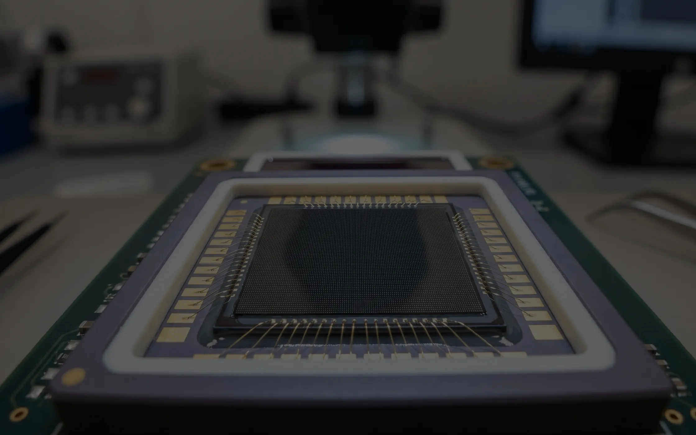
- Uncooled infrared detectors: the absorber layer is typically vanadium oxide (VOx) or amorphous silicon (a-Si), suspended on a micro-bridge above the silicon substrate so incoming radiation converts into a measurable temperature rise. The temperature coefficient of resistance (TCR) is extremely sensitive to lattice state and stoichiometry, and sustained heat above 120 °C causes irreversible drift that shows up as a worse noise equivalent temperature difference (NETD) and lost measurement accuracy. The cavity is a milli-torr-class vacuum, and higher cure temperatures drive more aggressive outgassing from internal surfaces, which exhausts the getter faster and shortens vacuum life.
- Thermal print heads (TPH): an alumina ceramic substrate carries the heater resistor array, the driver ICs and an aluminum heat sink. Aluminum expands at roughly 23 ppm/°C against about 7 ppm/°C for alumina, a factor of three in linear coefficient of thermal expansion (CTE). During a 120 °C cure and the cool-down that follows, interfacial shear stress drives macroscopic bowing, contact pressure against the thermal paper goes uneven, and the result is broken print lines or uneven density. Thin-film heater arrays now rise within hundred-microsecond time constants, and they are more sensitive to substrate flatness than thick-film designs.
- CMOS image sensors (CIS): color filters and micro-lens arrays are built from organic pigment and photoresist systems, and heat deforms them, lowers transmittance and raises dark current. Wafer-level packaging (WLP) and chip-on-board (COB) flows add interlayer dielectric delamination risk.
- Polymer optics: polycarbonate (PC), cyclo olefin copolymer (COC) and cyclo olefin polymer (COP) lenses mostly transition between 100 °C and 150 °C, and long bakes soften them or cause irreversible yellowing.
- Flex substrates: polyethylene terephthalate (PET) transitions at around 78 °C with an even lower Vicat softening point. Polyimide (PI) itself holds up better, but the components sharing the same assembly are usually the limiting factor. High-temperature cure induces shrinkage, curling and pad displacement.
Stack those constraints and the heat budget left to structural bonding is the band below 100 °C, with outgassing, ion purity and interfacial stress still to protect.
Low-temperature cure is not the better route in every case. Where a device imposes no thermal budget constraint, cure at 120 °C or above stays the first choice, with wider crosslink density, a higher temperature ceiling and more functional formulation space. What usually caps this route is Tg being pinned at the cure temperature. SCITEO holds a measured Tg of 120 °C (DMA) inside the 60 °C to 80 °C window through rigid backbone resin and high crosslink density design, rather than trading temperature capability away for low temperature.
Three Failure Chains Behind High-Temperature Cure
Loss from high-temperature cure is not a single failure mode. It runs along three chains, landing on electrical parameters, mechanical structure and intrinsic material properties.
Calibration drift in thermal-sensitive films is the hardest to recover from. The temperature coefficient of resistance in vanadium oxide and amorphous silicon depends on microstructure and oxygen content. Heat input triggers microscopic lattice rearrangement, and the calibration curve shifts before the device ever ships. No back-end algorithm compensates for that. It is a material-level scrap.
Thermomechanical stress across dissimilar interfaces releases during cool-down. Coefficient-of-thermal-expansion differences among ceramic, aluminum, silicon, glass and organic substrates convert into interfacial shear and warpage. On a thermal print head that breaks the flatness budget. On a camera module it shifts the optical axis and defocuses the assembly.
The third chain is phase change and deformation in organic materials. Color filters, micro-lenses, polymer optics and low-Tg substrates enter the rubbery state under heat and keep residual deformation after cooling. Combine that with condensable volatiles from the adhesive and you get the fogging contamination routinely found inside camera cavities.
Low-Temperature Cure Is Already the Industry Default
Low-temperature cure is no longer only defensive. Roadmaps are turning the boundary into a design precondition.
Infrared detector packaging shows the shift most clearly. Wafer-level vacuum packaging integrates the vacuum cavity, the getter and the optical window into wafer-level processes, so detectors assemble in standard environments without a Class 100 cleanroom and stay compatible with SMT lines. With an 8 μm pixel pitch and 640×512 resolution, the core measures 11.2 mm × 11.2 mm at under 1 g, draws under 120 mW, holds NETD below 50 mK and shrinks about 74% against a conventional ceramic package. That route presses two conflicting requirements onto one detector: die attach and lid sealing inside the cavity have to run with low outgassing, while module-level assembly still passes through 260 °C reflow.
Demand is expanding in parallel. Thermal imaging has moved well beyond security and industrial thermography into automotive night vision, commercial drones supporting the low-altitude economy, embodied-AI robots and wearables, which tightens size, weight and power (SWaP) budgets while raising expectations on temperature range and image quality.
Material markets point the same way. The global low-temperature cure adhesive market has moved into the USD 680 million class and is advancing toward USD 1.06 billion, at a compound annual growth rate around 6.5%, with epoxy systems holding roughly 60% of the mix and Asia-Pacific contributing close to half the revenue. The more telling number is the qualification barrier. Requirements on cure window, Tg, ion content and coefficient of thermal expansion tighten every year, and only a limited set of suppliers clear core certifications such as J-STD-020, AEC-Q200 and UL94 V-0 together. Domestic suppliers have gained share over the past two years mainly through that certification coverage and proven process fit. Average cooperation between top-tier customers and their material suppliers runs beyond six years with renewal rates above 90%, which says the relationship is anchored on process service rather than on a quoted price.
Put cure window, structural strength, low outgassing and reflow tolerance on one adhesive, and the list of epoxy systems that deliver all four is short; that combination is where the bar in thermal-sensitive packaging sits.
Why 60-80 °C Became the Workhorse Window
Lowering cure temperature and preserving room-temperature shelf life pull in opposite directions. The 60 °C to 80 °C band became the workhorse window because it leaves engineering margin on both sides of that conflict.
Arrhenius Kinetics Against Storage Stability
The temperature dependence of the reaction rate constant follows the Arrhenius equation. A higher activation energy makes the rate less temperature-sensitive, slows the room-temperature dark reaction and improves shelf life. For the same reason it caps the reaction rate available inside a low-temperature window. Dropping cure temperature from 120 °C into the 60 °C to 80 °C band while keeping an acceptable takt time leaves one direction: raise the intrinsic activity of the curing agent and put the rate burden on chemical structure rather than heat. A high-activity curing agent at 25 °C typically holds only tens of minutes of pot life, and the dispense line gels before the shift ends. That is the knot a low-temperature formulation has to untie first.
De-Blocking Threshold of a Latent Curing Agent
SCITEO separates activity from stability in space rather than in chemistry. A modified amine curing agent is fully encapsulated in a polymer shell to form a core-shell microcapsule. At −20 °C storage and at room temperature the curing agent stays dormant, and the paste holds stable viscosity and working life. Once the substrate enters the set threshold, the shell melts and ruptures, the curing agent releases quickly and ring-opening polymerization of the epoxy groups completes three-dimensional crosslinking on a 15-minute scale.
De-blocking temperature is confirmed by differential scanning calorimetry, where a clear exothermic peak appears. Peak position and integrated enthalpy together define the cure window. That is also why the 60 °C, 70 °C and 80 °C grades each need their own shell structure: the gap looks like 10 °C, but it corresponds to three different de-blocking kinetics, and running one adhesive colder is the most common process misjudgment in this category. The same mechanism explains why cold-chain storage is mandatory. Higher thermal activity means a faster room-temperature dark reaction, and once logistics leave temperature control, viscosity climbs until the paste leaves the processable range of the dispenser.
At this end of the range, 55 °C is a grade SCITEO builds specifically for extreme thermal-sensitive processes, and it requires its own curing-agent shell architecture. It currently serves only interfaces that tolerate no excess heat at all, such as vanadium oxide absorber films and amorphous silicon micro-bridge structures. That population is small, but without a lower trigger temperature the device cannot be built at all.
Rebuilding Crosslink Density in a Low-Temperature Window
Low-temperature cure has long been criticized for weak mechanical strength, and the root cause is crosslink density. Density is set by functional group count and reaction completion. A low-temperature window leaves less time for segment mobility, and two-part systems add mixing-ratio deviation and entrapped air on top of that, which is why conventional low-temperature adhesives rarely pass 10 MPa shear.
Single-component latent systems win here. Once de-blocking starts, the curing agent releases uniformly, functional groups react at stoichiometric ratio, and with multi-functional epoxy and rigid backbone resin selection the crosslink density builds fully inside the 60 °C to 80 °C window. This system reaches above 18 MPa die shear on gold-plated pads, alumina ceramic and bare silicon, and 24 MPa on etched aluminum. The typical failure mode in destructive push testing is ceramic substrate fracture rather than bond line peel, which means interfacial adhesion already exceeds the strength of the substrate itself. When we run die shear tests we log two values, the force and the fracture location. A strength number alone cannot separate interfacial failure from cohesive failure, and those two outcomes point at completely different corrective actions.
Low Stress, Low Moisture and Electrical Insulation Delivered Together
Structural strength is only the entry ticket. A thermal-sensitive interface demands three properties in parallel: low stress, low moisture absorption and electrical insulation.
- Low stress: cure linear shrinkage held below 0.6% (ISO 2577) combined with a graded low-modulus design releases interfacial stress during cure instead of banking it for the next thermal cycle.
- Low moisture: water absorption of 0.03% means very little moisture enters the bond line under humid conditions, which cuts the vapor source behind the popcorn effect and removes the transport medium for electrochemical migration.
- Electrical insulation: volume resistivity of 1.8×10¹⁴ Ω·cm (ASTM D257) together with extractable ion content at or below 10 ppm (IC ion chromatography) keeps leakage current and insulation decay inside acceptable limits under humid bias.
Only when those three hold at once does a system qualify for infrared detector vacuum packaging and reflow-tolerant interfaces. Formulations that trade strength for low temperature usually stop at this step.
Core Performance Metrics and Acceptance Criteria
Procurement review turns on whether each figure lands on a test method, a boundary condition and a failure mode, not on how many rows a datasheet carries.
Die Shear Strength and Failure Mode
Interface strength needs two lanes: tensile lap-shear coupons to GB/T 7124 for lot-to-lot stability of the adhesive and the process, and die shear to MIL-STD-883 Method 2019 for the margin on the real interface. The test has to lock onto the actual substrate and metallization, because the same adhesive can differ several times over across gold plating, alumina ceramic, bare silicon, etched aluminum and polyimide; the release specification should state substrate condition and bond line thickness. SCITEO reports ≥18 MPa on gold-plated, ceramic and bare silicon interfaces and 24 MPa on etched aluminum, together with the fracture location, so process engineers can judge whether the interfacial margin carries the mechanical loads of downstream operations.
260 °C Reflow Tolerance and the Popcorn Effect
Reflow tolerance tests the stability of the fully cured network and the level of moisture control. After moisture sensitivity level (MSL) preconditioning per J-STD-020, samples must survive multiple reflow cycles at a 260 °C peak, judged on no bond line cracking, no interfacial delamination, no popcorn effect, and shear strength retention afterwards. The popcorn mechanism is vaporization of absorbed moisture: water flashes to vapor at peak temperature and steam pressure lifts the bond line. Holding water absorption at 0.03% removes most of that vapor source at the origin, and that is what puts a low-temperature system onto an SMT line in practice.
Strength Retention after Damp Heat and Temperature Cycling
Initial strength proves the cure completed. Long-term reliability is decided by retention after aging. Run 85 °C/85% RH temperature-humidity bias (THB) aging to JESD22-A101 and temperature cycling (TC) to JESD22-A104, and combine them with reflow and cleaning steps into a sequence so cumulative decay becomes visible; read the two tests in isolation and the number is usually flattering but unrepresentative. For a low-temperature system the acceptance line collapses into one question: are shear retention and insulation resistance still inside the release window after aging.
Outgassing, Ion Purity and Vacuum Cavity Cleanliness
Outgassing control is a hard requirement for infrared detectors and optical modules. Measured to ASTM E595, collected volatile condensable materials must stay below 0.05%, and cure must not release low-molecular condensates that fog optical windows and micro-lens surfaces. Inside a vacuum cavity, outgassing carries a second, quantitative meaning. Getter capacity is finite, and water vapor, carbon monoxide and carbon dioxide released during sealing and aging consume that capacity directly, converting into vacuum life. Keeping outgassing low reserves vacuum margin for the cavity.
Extractable ions run as a parallel risk line and are the direct driver of electrochemical migration (ECM). Chloride, sodium and potassium ions act as electrolytes under humid bias, accelerate anodic dissolution of metallization and drive conductive anodic filament (CAF) growth and leakage creep. Electronic-grade purified resin with passivated filler surfaces holds extractable ions at or below 10 ppm, which is the floor for insulation reliability in humid service.
Rheology and Production Takt
Line yield is set by rheological structure matched to takt time. A low-temperature system has to keep a stable thixotropic structure even after cold-chain storage: a thixotropic index of 5 to 6 with more than 80% viscosity recovery within one second of shear removal, so the same formulation runs on 25G precision needles, jetting valves and stencil printing without stringing or slump. Dot height and area consistency set bond line thickness distribution, which in turn sets interfacial stress and sealing reliability. For fine-pitch work SCITEO matches needle bore to maximum filler particle size and keeps a viscosity range of 1500 to 280000 mPa·s available across dispensing methods.
Selected Thermal-Sensitive Interfaces
Selection logic for low-temperature cure is reverse-engineered from failure modes on the device side and has little to do with a sorted datasheet. The interfaces below cover the cases in thermal-sensitive packaging most worth spelling out, and the same failure mechanisms carry over to the rest of the device population.
Uncooled Infrared Detectors and MEMS Vacuum Packaging
Infrared detectors stack two heat constraints. Inside the cavity, die attach and lid sealing must cure below the phase-change window of the absorber film while keeping outgassing low enough to protect the vacuum. Outside, wafer-level packaging makes the detector SMT-compatible, so the packaged part also has to survive reflow. MEMS structures are suspended inside that cavity and are equally sensitive to residual stress and particle contamination. Routine thermal-sensitive interfaces can run the 60 °C to 80 °C window; extreme cases such as vanadium oxide films and micro-bridge structures inside a vacuum cavity are where the 55 °C custom grade comes in. That grade holds cure heat low enough that the calibration curve barely moves, while still delivering ≥18 MPa shear for vibration and shock duty.
Deployment is spreading quickly. Automotive night vision, commercial drones and industrial thermography keep tightening size, weight and power budgets, and the process window narrows with them. On these interfaces, low-stress cure and a low-moisture backbone pay off as calibration stability and converged zero-point drift over the product lifetime.
Thermal Print Heads and Ceramic-to-Aluminum Assemblies
The core process in a thermal print head is large-area dissimilar bonding. The alumina substrate and the aluminum heat sink must conduct and insulate at the same time while holding flatness. A 60 °C to 80 °C window minimizes thermomechanical stress during cool-down, suppresses bowing, keeps contact pressure against the thermal paper even, and holds flatness in the micron range. Thin-film heater arrays are even more sensitive to substrate flatness, and bond line thickness uniformity decides print density uniformity. Delivery on this interface centers on structural bonding and sealing, and SCITEO reports shrinkage and water absorption alongside strength.
CMOS Camera Modules and Precision Optical Bonding
Automotive camera modules now lead with 8 MP front sensing and must hold imaging stability from −40 °C to +105 °C, which sets three requirements for structural bonding. Cure temperature has to stay below the deformation threshold of color filters and micro-lens arrays, with the IR-cut filter coating and resin layers especially sensitive. Cure displacement has to be predictable, because after active alignment (AA) the bonding of the lens barrel, the filter and the voice coil motor (VCM) base introduces displacement and shrinkage, and lower cure shrinkage translates directly into better optical axis stability. And cavity cleanliness has to be controlled, because condensed volatiles degrade both focus and image quality at the same time. SCITEO delivers a low-outgassing grade at CVCM below 0.05% for this interface, with ion content controlled in the same specification to suppress electrochemical migration under humidity.
Flexible Circuits, Foldable Devices and AI Glasses
Flexible printed circuits (FPC) are among the most certain low-temperature cure applications. The hinge region of a foldable display takes hundreds of thousands of dynamic bends, and the flex carrying signals across the display is held in shape by stiffening and sealing layers, so the adhesive has to be low-modulus, bend-tolerant and curable below the Vicat softening point of the substrate. Polyimide and polyethylene terephthalate shrink and curl above 100 °C, and low-temperature cure takes that risk out of the process chain. AI glasses push the same constraint further: the temple interior is measured in millimeters, flex circuits, microdisplays and sensors share one structure, and weight and reliability pull against each other. Low-temperature cure with low outgassing is the precondition for these assemblies to exist.
Medical Sensing and Life-Information Devices
Life-information devices and wearable monitors press low-modulus polymers, precision electrodes and flexible substrates into one patch, so the encapsulant has to seal, buffer deformation and clear two cleanliness gates on ions and outgassing. Once cure temperature is decoupled from the device temperature ceiling, a 60 °C to 80 °C window clears the softening range of thermoplastic polyurethane and textile substrates, low-stress cure avoids stress concentration at electrode interfaces, and a low-moisture backbone reduces leakage and drift risk during long wear cycles.
Production Control: Cold Chain, Dispensing and the Curing Platform
Low-temperature systems demand more process discipline than conventional single-component epoxy. Cold chain, dispensing and cure are three links in one chain, and a deviation anywhere in it gets amplified in shear strength and void rate.
Cold Chain and Warm-Up Discipline
- Full cold chain: factory-out and transport use dry-ice temperature-controlled packaging that keeps the room-temperature dark reaction blocked for the whole logistics chain.
- Mandatory frozen storage: transfer to −20 °C storage within 30 minutes of receipt. Vacuum packaging extends storage stability further.
- Graded warm-up: hold the unopened package at room temperature for at least two hours before use. Never accelerate warm-up with an oven, hot water or hot air. A cold syringe surface condenses ambient moisture instantly, and free water inside the adhesive flashes to vapor during cure, leaving micro-voids that destroy shear strength and dielectric withstand.
- Work-cell control: keep the dispensing area below 30 °C, use warmed material within 24 hours below 25 °C, and reseal and return any remainder to cold storage immediately.
Dispensing and Bond Line Geometry
Jetting or stencil printing is preferred to reduce shear-history variation. During continuous dispensing, monitor thixotropic recovery time and needle clogging. When stringing or dot slump appears, check warm-up completeness and needle bore against maximum filler particle size before touching the formulation. For the small-dot interfaces found in infrared detectors and optical modules, dots must be round with no tailing, and dot height consistency sets sealing reliability.
Precision Temperature Control on a High-End Line
The 60 °C to 80 °C window does not carry the ±5 °C or better of margin a 120 °C process enjoys. Whether it works comes down to the temperature control capability of the line itself.
The equipment baseline is a high-precision uniform-temperature platform: working-zone uniformity within ±3 °C, which is AMS2750 Class 1, the tightest furnace class in the specification, together with a programmable ramp rate, forced-convection circulation and multi-point temperature logging. Acceptance for furnace uniformity and thermocouple system accuracy can be anchored to ASTM E145-19(2024) and AMS2750. A single-point control scheme can hold its own setpoint perfectly while the rest of the chamber drifts, and the core of a bonded assembly lags the ambient temperature, so a few degrees of spread is written into the DSC curve as a stratified degree of cure.
The rigor of the measurement side decides whether the window can be reproduced reliably. A temperature uniformity survey (TUS) stabilizes the furnace at the test temperature, places a grid of calibrated survey thermocouples through the working zone, records the highest and lowest readings, the spread in heat-up time across sensors and the fluctuation during the steady-state hold, and defines the qualified working zone from that data. Sensor placement has to cover the four corners, the center, the cold zone near the door, the hot zone where supply air lands, and any top-to-bottom stratification, with the count scaling by working-zone volume, typically nine points for zones up to about 3 cubic feet. The survey has to run under load. An empty-chamber result stops being valid the moment thermal mass enters the picture.
One tier higher, the measurement target moves from ambient temperature to part temperature and interface temperature. Load thermocouples bonded to the substrate surface take the reading off the equipment panel; fiber Bragg grating (FBG) sensors can be embedded into the bond interface and resolve temperature and strain at each coordinate in real time, capturing the cure exotherm and the gel point together; dielectric analysis (DEA) per ASTM E2038 and E2039 tracks ion viscosity across multiple in-line channels and outputs degree-of-cure and glass-transition evolution directly. Stack those three and the release question changes from does the furnace hold setpoint to is the adhesive itself in the right state.
A stepped ramp and per-lot degree-of-cure confirmation are routine actions here and follow the criteria above. The dividing line is whether a line has loaded-survey and multi-channel logging capability at all, and that capability is itself a marker of high-end manufacturing. On builds like these, SCITEO brings profile calibration into the qualification stage, aligning the adhesive cure window against the customer's measured equipment curve so a capability mismatch does not surface only at ramp-to-volume.
Inspection and Release Criteria
Run die shear on a lot sampling basis for mechanical release, inspect void distribution with scanning acoustic microscopy (SAM) and X-ray for the interface, and sample insulation resistance on the electrical side. Grade release criteria by application: hold void area fraction within 10% for consumer and industrial packages, tighten to 5% for optical, medical and high-reliability builds, and put shear retention and insulation resistance after damp heat and temperature cycling into routine monitoring. SCITEO reports both force and fracture location, and process support covers syringe, jetting and stencil routes so the cure window transfers into volume production in one pass.
Low-Temp Cure Adhesive Selection Reference
The table compresses the mechanisms above into executable selection criteria for packaging and process engineers at review:
| Application | Typical Failure Mode | Primary Criteria | SCITEO Direction |
|---|---|---|---|
| Uncooled infrared detector vacuum packaging | Absorber film resistance drift, vacuum decay from outgassing | 55 °C custom grade, CVCM below 0.05%, low water absorption | Low-temperature cure epoxy (extreme thermal-sensitive grade) |
| MEMS sensor hermetic packaging | Package warpage, zero-point drift, seal failure | 80 °C cure, shrinkage below 0.6%, low stress | Low-temperature cure epoxy (low-stress grade) |
| Thermal print heads and heater assemblies | Ceramic-to-aluminum bowing, flatness out of tolerance | 60-80 °C cure, low shrinkage, large-area uniformity | Low-temperature cure epoxy (structural bonding grade) |
| CMOS camera modules and optical structures | Filter and micro-lens deformation, cavity fogging | Low-temperature cure, low outgassing, low cure displacement | Low-temperature cure epoxy (low-outgassing grade) |
| Flex circuits, foldable devices and AI glasses | Substrate shrinkage and curling, bend cracking | Cure below 100 °C, low modulus, bend durability | Low-temperature cure epoxy (low-modulus grade) |
| Medical sensing and life-information devices | Electrode stress concentration, drift during wear | Low ions, low outgassing, low-modulus buffering | Low-temperature cure epoxy (clean grade) |
| General 3C structural assembly and sealing | Component heat damage, insufficient dielectric withstand | 60-80 °C cure, ≥18 MPa, 1.8×10¹⁴ Ω·cm | Low-temperature cure epoxy platform |
Conclusion
Once a thermal-sensitive device has gone through its definition stage on a thermal budget, bringing the temperature down later moves more than one adhesive. It moves the cold chain, the dispensing process, the curing platform and the burn-in sequence, along with the engineering change cost that follows. The value of a low-temperature cure system is leaving that path open early; reopening the process after yield has gone wrong costs far more.
That is also why SCITEO treats low-temperature cure as a complete product line rather than a single adhesive. The formulation is only the starting point: the same cure window delivers stable volume production on a line with loaded-survey capability, and lot-to-lot scatter on a line with coarse temperature control. Whether low-temperature cure is usable depends on whether material and manufacturing conditions are matched; a datasheet on one adhesive will not answer it.
This article is SCITEO Advanced Materials original technical content; unauthorized reproduction is prohibited.
Appendix: Process & Engineering Adhesive FAQ Index
Many single-component adhesives claim a 60 °C cure with no cold-chain shipping. Why does SCITEO treat that as unreliable?
Activation energy settles it. A single-component system that stays stable at room temperature for months must have a high activation energy, and a high activation energy cannot deliver the reaction rate a deep 60 °C cure needs. Such grades typically skin over during a 60 °C bake while the interior stays largely uncured, with measured shear below 5 MPa per GB/T 7124 and pulverization under later shock and push testing. A system that triggers at 60 °C and still reaches full crosslinking depends on cold-chain logistics end to end to block the room-temperature dark reaction.
If a low-temperature cure adhesive cannot take heat, how does it pass 260 °C SMT reflow?
Separate the uncured and cured states. Before cure, the paste being triggered by heat is the design intent. After full cure inside the 60 °C to 80 °C window, the material forms a dense, rigid three-dimensional thermoset network in which chain segments are locked by chemical crosslinks and nothing can flow. In a 260 °C peak reflow cycle per J-STD-020, that network neither melts nor breaks its backbone within the seconds of the excursion, so mechanical anchoring holds and the popcorn effect does not appear.
Why do most production lines settle on 60-80 °C, and where does 55 °C fit?
The 60 °C to 80 °C band is the mainstream process window for low-temperature thermosetting structural adhesives today. Heat-sensitive materials used in flexible substrates and OLED displays generally require cure below 80 °C, and this band balances takt time, degree of cure and equipment cost at once. The 55 °C grade is an extreme tier, reserved for interfaces that tolerate no excess heat at all, such as vanadium oxide absorber films and micro-bridge structures inside a vacuum cavity. The two tiers run on independent shell structures and independent de-blocking kinetics, so running one adhesive colder is not an option, and any temperature-time equivalence must be verified by DSC residual enthalpy rather than estimated from experience.
Does low-temperature cure sacrifice shear strength or insulation performance?
Only when crosslink density never gets built. This system reaches above 18 MPa die shear on gold-plated pads, alumina ceramic and bare silicon, evaluated with tensile lap-shear coupons to GB/T 7124 for lot-to-lot stability and die shear to MIL-STD-883 Method 2019 on the real interface, and 24 MPa on etched aluminum. Destructive push tests more often show the substrate cracking before the bond line peels. On the electrical side, volume resistivity holds at the 1.8×10¹⁴ Ω·cm level per ASTM D257 and cure linear shrinkage stays below 0.6% per ISO 2577. Low shrinkage and low moisture protect insulation and sealing margin together, so strength is not the currency being spent on temperature.
Cure temperature is only 80 °C. How high can Tg go, and does it drop after reflow?
This system measures a glass transition temperature of 120 °C by DMA, taken at the storage modulus inflection and 40 °C above the cure temperature itself. Low-temperature systems commonly let Tg sit at the cure temperature, and a Tg of 60 °C to 90 °C decays quickly once service temperature climbs, which is why low-temperature adhesives have long been treated as short-lived. We open that gap with a rigid backbone resin and high crosslink density while holding cure linear shrinkage below 0.6%. A 260 °C peak reflow is a seconds-long excursion that does not break the network backbone, so Tg and shear retention after reflow stay inside the release window. Long-term temperature capability is better read from the aged modulus plateau: run DMA again after damp heat and temperature cycling rather than trusting the as-cured number.
Can a 120 °C oven and a sub-80 °C low-temperature system share the same curing platform?
Not directly. A conventional 120 °C process tolerates ±5 °C of furnace deviation or more, while the 60 °C to 80 °C window is far more sensitive to heat flux. The equipment side needs working-zone uniformity at the AMS2750 Class 1 level of ±3 °C, plus a programmable ramp rate, forced convection and multi-point thermocouple logging. Calibration must use a thermocouple bonded to the actual substrate surface to build the profile, not the equipment setpoint readout. A low-temperature window is narrow, and a few degrees of spread shows up as a stratified degree of cure on the DSC curve and as scattered push-test data.
Why does cold chain and warm-up discipline matter that much?
Low-temperature systems are far more reactive than conventional single-component epoxies, and any logistics gap outside temperature control raises viscosity until the material leaves the processable window. The warm-up step carries a subtler risk: a cold syringe surface condenses ambient moisture instantly, and free water inside the adhesive flashes to vapor during cure, forming micro-voids that collapse shear strength and dielectric withstand at the same time. Hold unopened packaging at room temperature for at least two hours, never accelerate warm-up with an oven, hot water or hot air, and use warmed material within 24 hours below 25 °C.