Cryogenic Adhesive Selection: −55 °C to −255 °C Bonding Failure Physics and Interface Materials for LNG, Superconducting Magnets and Quantum Computing
From LNG shipping and liquid hydrogen tanks to superconducting magnet impregnation and quantum cryo-packaging: how SCITEO engineers stress management into cryogenic interface materials
Abstract
Cryogenic bond failure almost never shows up in room-temperature data. Below −55 °C, polymer chain segments freeze, storage modulus climbs by an order of magnitude, and fracture toughness falls in the same direction. The material loses its ability to dissipate stress through deformation, and the conflict moves to the interface: aluminum alloys run about 23-24 ppm/°C and austenitic stainless steel about 16-17 ppm/°C, while unfilled epoxy sits at 45-60 ppm/°C. Cooled from room temperature to −196 °C, aluminum contracts roughly 0.4% by integral length change and the unfilled bond line nearly twice that. On a meter-scale bonded area the difference accumulates to millimeters, and every millimeter of it converts into shear stress across the bond line.
One-line conclusion: whether a cryogenic bond stays reliable comes down to the combination of low-temperature fracture toughness, interfacial anchoring strength and residual cure stress. Room-temperature shear strength is not the deciding number.
SCITEO Advanced Materials works backward from the application to design its cryogenic platforms. The first step is to map the real stress spectrum a device sees in LNG shipping, liquid hydrogen tanks, superconducting magnets, cryogen-free MRI scanners and dilution refrigerators. The second is to translate that spectrum into resin backbone, toughening phase, filler grading and cure window. What follows walks through failure physics and formulation logic first, then the product matrix, field applications, reliability data and process execution, across the full −55 °C to −255 °C range, and closes with a selection framework for liquid-nitrogen-grade epoxy modulus control that can be used directly.
Key Parameters at a Glance
The table sets SCITEO cryogenic systems next to conventional low-temperature adhesives:
| Parameter | SCITEO | Industry Baseline | Test Standard |
|---|---|---|---|
| Minimum service temperature | −55 °C to −255 °C | −40 °C to −60 °C | LN₂ immersion / low-temperature dwell |
| Room-temperature shear strength | ≥32 MPa | 8-15 MPa | GB/T 7124 |
| Peel strength | 26 pli | 5-12 pli | ASTM D1876 |
| Fracture toughness KIC at LN₂ | ≥5.3 MPa√m | 1.5-2.5 MPa√m | Three-point bend at LN₂ temperature |
| Cure linear shrinkage | 0.05%-0.2% | 1%-3% | ISO 2577 |
| Volume resistivity | 10¹⁵ Ω·cm | 10¹²-10¹³ Ω·cm | ASTM D257 |
| CVCM | <0.1% | >1% | ASTM E595 |
Why Cryogenic Bonds Fail: CTE Mismatch, Modulus Freezing and Fracture Toughness Collapse
Engineering practice treats −55 °C and below as cryogenic service, and that boundary is physical rather than arbitrary. General-purpose polyurethane structural adhesives lose toughness near −50 °C, conventional silicones degrade quickly past −60 °C, and the liquid nitrogen (−196 °C) and liquid helium (−269 °C) ranges sit deep inside the glassy state. Cross that line and the governing failure mode shifts from insufficient strength to stress that cannot be released.
Thermal Expansion Mismatch and Accumulated Displacement
Organic polymers expand and contract far more than metals or ceramics, and the gap widens in the cryogenic range. Room-temperature instantaneous values and cryogenic integrals have to be read separately: heat capacity and expansivity both decay as temperature drops, so what engineering calculations actually need is the integral contraction from room temperature to the target temperature.
- Aluminum 6061 class: about 23-24 ppm/°C at room temperature, roughly 0.4% integral contraction from 300 K to 77 K
- Austenitic stainless steel 304/316: about 16-17 ppm/°C, roughly 0.3% over the same span
- Carbon fiber composites: 0-5 ppm/°C in the fiber direction, markedly higher transverse
- Unfilled epoxy: 45-60 ppm/°C
- Silica-filled epoxy: down to 20-30 ppm/°C
Cooled from room temperature to −196 °C, an aluminum substrate contracts about 0.4% and an unfilled epoxy bond line nearly twice that. On a millimeter-scale bond area the difference is a micron-level offset. On a meter-scale bonded structure the accumulated displacement reaches millimeters and loads the interface with continuous shear and peel coupling. Most cryogenic structural failures trace back to that one differential.
Modulus Freezing in the Deep Glassy State
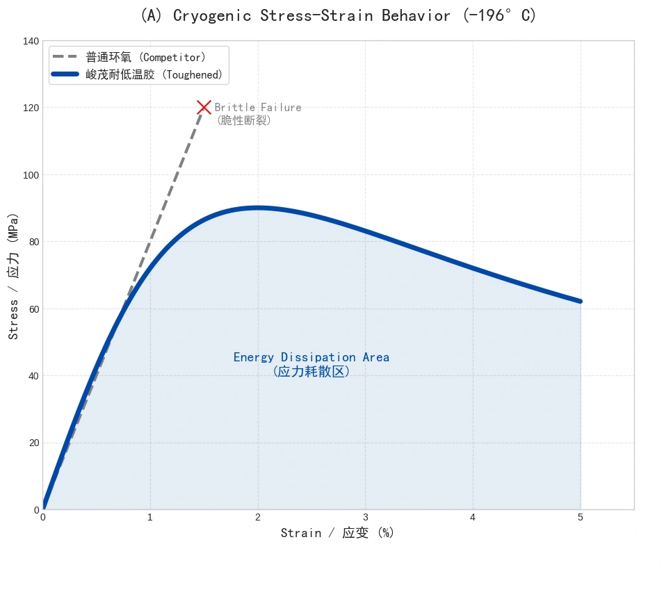
Once a conventional epoxy enters the deep glassy state, chain segments are fully immobilized and storage modulus surges into the 5-8 GPa range. The material shifts from semi-rigid to high-modulus brittle. Any accumulated stress above its fracture toughness KIC then produces instantaneous brittle cracking through the adhesive body, or delamination from the substrate.
Fracture toughness is the most frequently skipped selection parameter. Published data puts a base bisphenol-A epoxy cured with an aromatic amine at roughly 2.0 MPa√m at liquid nitrogen temperature; swap the rigid benzene rings for flexible aliphatic segments and the same test can be pushed into the 5.3 MPa√m range, which is the route SCITEO's extreme-cryogenic line follows to hold deep-cryogenic fracture toughness at that level. Toughening performance shows up directly in fracture toughness, and room-temperature shear strength gives no read on it.
Micro-Crack Accumulation and Cryogenic Thermal Fatigue
Cryogenic damage accumulates. Every cooldown either initiates new micro-cracks or extends existing ones, and after enough cycles the crack network connects. Sealing and insulation degrade together, cryogenic fluid penetrates the cracks, expands on warm-up, and accelerates interfacial failure. That is the physical reason cycle count belongs in the selection criteria: surviving one cooldown says nothing about surviving fifty.
Molecular Architecture: Keeping Chain Segments Mobile at Liquid Nitrogen Temperature
Epoxy already delivers enough bond strength and process controllability. The gap sits in stress management, and that is where SCITEO's cryogenic platforms start, with the adjustable variables concentrated in backbone, toughening phase, interfacial anchoring and filler system.
Long-Chain Aliphatic Backbone with Flexible Ether Linkages
For the −196 °C to −255 °C range, SCITEO reduces the proportion of rigid benzene rings in the resin backbone and introduces long-chain aliphatic structures with retained flexible ether linkages. The resulting network keeps a limited degree of chain rotation and creep capability in deep cryogenic service, so when CTE mismatch generates contraction tension the bond line dissipates concentrated stress through molecular chain slippage instead of passing the stress spike straight into the interface. Put a number on that: storage modulus in this line holds in the 2,300 MPa range at cryogenic temperature instead of climbing by multiples the way a conventional epoxy does, which is what leaves the bond line with deformation capacity to absorb stress at liquid nitrogen temperature.
Core-Shell Rubber and Liquid Rubber Co-Toughening
To raise fracture toughness further, SCITEO disperses core-shell rubber (CSR) particles uniformly through the system and pairs them with liquid rubber to build a multi-scale toughening phase. The polybutadiene core of CSR particles has a glass transition temperature near −80 °C, and the rubber phase of the liquid rubber sits between −70 °C and −80 °C, so both stay rubbery at liquid nitrogen temperature and the toughening mechanisms are never frozen out:
- Cavitation: under contraction load the rubber cores cavitate internally, releasing the hydrostatic pressure built up by volume shrinkage
- Shear yielding: the particles induce plastic shear bands in the surrounding epoxy matrix, blunting crack tips and arresting propagation
- Crack deflection: the size hierarchy across toughening phases forces the crack to change direction repeatedly, raising the energy required to extend it
Interfacial Anchoring and Peel Strength
SCITEO cryogenic systems reach 26 pli peel strength, which sits in the upper band for a structural rigid adhesive, with room-temperature shear strength above 32 MPa. High peel strength buys interfacial anchoring: when the bond line contracts, interfacial bonding holds the adhesive in place and forces it to deform elastically, which keeps the interface from opening. The dominant load on a cryogenic interface is peel and shear acting together, and shear strength alone gives no read on that.
Two Filler Branches with Opposite Objectives
Filler selection is directional in cryogenic service.
For −55 °C, −60 °C and −70 °C duty, the formulation raises the thermally conductive filler ratio to hit 1.5 W/m·K and 90 Shore D or higher. This branch is built for rigid fixation of components and suppression of vibration displacement, with a conduction path that limits local temperature rise so sensors and precision parts hold their mechanical integrity through thermal shock.
Drop to −200 °C or −255 °C and the filler ratio has to come down instead, holding hardness near 60 Shore D and putting matrix elongation and low-temperature toughness first. Thermal conductivity gives up some ground, but the cracking margin it buys is decisive at liquid nitrogen temperature.
SCITEO Cryogenic Product Matrix
Rather than stretch one formulation across every temperature grade, SCITEO supplies a graded matrix that runs from military thermal shock duty to the liquid helium range.
| Product Series | Minimum Service Temperature | Key Characteristics | Typical Applications |
|---|---|---|---|
| Low-Temperature High-Hardness | −55 °C / −60 °C | High strength with cold resistance, passes military thermal shock; −60 to 180 °C variant | Military connector potting, outdoor infrastructure sensors, automotive assembly |
| Low-Temperature Thermally Conductive | −60 °C / −70 °C | Strong cracking resistance, low Tg, low-viscosity conduction, low shrinkage | Military sensors, temperature probes, deep-well instruments, scientific equipment |
| Extreme Cryogenic | −196 °C / −255 °C | Validated through liquid nitrogen processes, high bond strength, low modulus, high peel toughness against micro-cracking, chemical resistant, stable electricals | LNG sensors, superconducting magnets, quantum computers, quantum chips |
Field Applications
How a cryogenic interface material should be selected follows from the stress spectrum the actual device carries. The six scenarios below are where SCITEO cryogenic systems do most of their work, and they also cover the technology routes scaling fastest right now.
LNG and Liquid Hydrogen: Cryogenic Pressure Sensors and Tank Sealing
Liquefied natural gas is stored near −162 °C at ambient pressure, and liquid hydrogen shipping runs as low as −253 °C. Leak detection in a cryogenic tank depends on continuous multipoint temperature mapping across the tank wall and base. Once insulation fails or the inner tank leaks, the resulting cold spot distorts the local temperature field and opens a window for flammable gas accumulation, so the temperature probes themselves must sit permanently in cryogenic fluid while holding electrical insulation.
The typical failure of a conventional sealant in this duty is low-temperature micro-cracking: once the bond line cracks, LNG penetrates the sensor body and causes short circuits and signal drift, and the fluid that has penetrated expands on warm-up and tears the adhesive further. SCITEO specifies a cryogenic-grade epoxy as the encapsulant and sealant for these probes. Hardness in the 60 Shore D range delivers toughness close to an engineering plastic, 26 pli peel strength absorbs the shear generated by stainless steel housing contraction, and a liquid nitrogen immersion screening run holds samples under continuous immersion for 500 hours with no interfacial separation on inspection.
Liquid hydrogen adds constraints. The dominant damage in filament-wound composite tanks under cryogenic load is matrix damage and fiber-matrix debonding, so the bonded interface has to deliver low permeability, low outgassing and cryogenic toughness at the same time. If the structure may contact liquid oxygen, the material also has to pass impact and friction sensitivity evaluation per ASTM G63 and NASA-STD-6001. Formulations for this duty control permeability through high crosslink density and bound vacuum-side cleanliness through the TML and CVCM thresholds of ASTM E595.
Commercial launch pushes the same duty into volume production. Medium and heavy liquid rockets use common-bulkhead tank structures for liquid oxygen with methane or hydrogen, loaded through deep-subcooled procedures, so tank seals, insulation retention and sensor terminal bonding all operate under combined cryogenic and vibration exposure over long service life, while reusability adds fatigue life requirements on structural parts. Formulation trade-offs here put cryogenic toughness, low outgassing and lot-to-lot consistency at the top, because a single point failure is enough to stop a launch flow.
Superconducting Magnets and Fusion: Vacuum Pressure Impregnation and Cryogenic Insulation
Winding insulation in a superconducting magnet is simultaneously the electrical barrier, a structural load path and a thermal conduction path. Niobium-titanium superconducts below roughly 9.2 K; niobium-tin must be wound before reaction at 650 °C to 700 °C; rare-earth barium copper oxide tape operates above liquid nitrogen temperature and supports 20 T class magnets. Windings are normally consolidated by vacuum pressure impregnation, which requires a resin that holds a low viscosity in the hundreds of centipoise for several hours of working time during impregnation, then delivers cryogenic toughness, low CTE, thermal conduction and radiation tolerance after cure.
That combination is inherently contradictory. Raising crosslink density improves low-temperature modulus and dimensional stability while reducing fracture toughness, and high-energy neutron irradiation in a fusion device drives chain scission and crosslinking failure. Insulation cracking and interfacial debonding can trigger a quench in low-temperature superconductors outright, or degrade the performance of high-temperature tape, which makes low-temperature fracture toughness of the insulation a first-order reliability variable.
SCITEO resolves that conflict along two axes. A mixed hardener system and multi-scale toughening phases let glass transition temperature and toughness be tuned independently, so the cryogenic modulus lands inside a window that carries electromagnetic loads without dumping the whole contraction stress budget into the interface. Low viscosity and long working time keep the formulation matched to the takt time of vacuum pressure impregnation on large coils.
Quantum Computing: Dilution Refrigerators and Millikelvin Cryo-Packaging
Superconducting qubits operate between 10 and 20 millikelvin, two orders of magnitude colder than the cosmic microwave background. Scaling from a single chip to multi-chip processors is forcing a rebuild of the cryogenic infrastructure: modular cryogenic architectures interconnect multiple refrigeration cells to host thousands of qubits per cryostat, signal routing inside dilution refrigerators is migrating from coaxial cables to flexible ribbon structures that cut heat load and speed up assembly, and wafer-scale packages are beginning to carry qubit arrays in the hundreds, with design effort redirected toward suppressing parasitic RF modes, reducing dielectric loss and managing differential thermal contraction.
That shift imposes a new constraint set on interface materials. Every temperature stage in a dilution refrigerator runs a strict cooling power budget, so any released cure stress, adhesive outgassing, or volatile condensable settling on a cold surface can contaminate the qubit surface and raise dielectric loss, which shows up directly as reduced coherence time. Differential thermal contraction acts simultaneously between package layer, interconnect layer and substrate, so the bonded interface needs enough compliance to absorb millimeter-scale offsets and keep that stress away from the quantum device.
For quantum hardware, the property list collapses to three items: low cure shrinkage to hold assembly geometry, low outgassing and low mobile ion content to protect dielectric loss and insulation, and low modulus with high elongation to absorb deep-cryogenic differential contraction. These requirements are shared with optical payloads and deep-space instrument hardware, and the cure window can be tuned per project on the same platform.
Superconducting Medical Equipment: The Interface Problem Behind Cryogen-Free Operation
MRI draws its main field from a superconducting magnet, and conventional platforms keep that magnet superconducting with liquid helium, so refill cycles and quench risk sit permanently on the operator's cost sheet. Medical imaging is also a major downstream helium user, so whenever helium supply tightens, cryogen-free operation stops being a cost exercise and becomes an engineering precondition. The mainstream route today is solid conduction cooling: the cold head of a two-stage cryocooler couples directly to the magnet, the assembly runs in the 4 K class, and no liquid helium sits inside the unit.
Under conduction cooling the magnet temperature settles at the balance point between cooling capacity and heat load, which turns the interface into the least visible link in the thermal chain. The adhesive layer and the thermal interface have to hold thermal resistance stable through repeated returns to room temperature, and stay compliant enough to absorb the small displacement between cold head and magnet rather than passing vibration into the superconducting joints. Outgassing and mobile ion content on the vacuum side then decide whether insulation and dielectric loss hold up over the long term, which is the same requirement a magnetoencephalography head array in that temperature class has to meet. On this temperature class, SCITEO's formulation platform solves low-modulus stress buffering, cryogenic thermal resistance stability and low outgassing in one material, instead of forcing a trade between three.
Large-Scale Facilities and Extreme Detection: Liquid Xenon, Liquid Argon and Deep-Space Infrared Payloads
Liquid xenon and liquid argon detectors and space infrared payloads look like two different worlds, particle physics and spaceborne remote sensing, but they select materials against the same criteria: cryogenic toughness, chemical inertness and low outgassing have to hold at once, because a single weak link is amplified by year-long immersion or by a cooldown span of hundreds of degrees.
Deep-underground low-background experiments immerse detectors in liquid xenon or liquid argon at roughly −100 °C and −186 °C respectively. These instruments use very large numbers of photodetection units across enormous optical areas, and they impose strict limits on the intrinsic radioactivity of every material that enters the detector, so each bonded component is screened and assayed for trace radioactivity. Bonded parts inside the detector must survive years of cryogenic immersion while meeting extremely low outgassing rates, because any volatile condensable that settles on an optical surface raises the background and costs light yield.
Space infrared payloads sit inside the same class of constraint. The instrument typically runs near 40 K, mid-infrared detectors need below 7 K, moving mechanisms may be allowed only tens of milliwatts, and a composite optical bench has to hold surface figure in the tens of nanometers across a cooldown span of hundreds of degrees. At that precision the bond line is part of the opto-mechanical structure: cure shrinkage, moisture expansion or low-temperature creep in the adhesive moves optical elements directly, shifting the optical path and degrading image quality.
Beyond those three, both duty classes also have to satisfy a low-background filler system, for photodetection unit fixation, insulating supports and sealing structures, and for optical element fixation plus detector assembly bonding. Cooldown in liquid xenon and liquid argon service is controlled and slow, but immersion is measured in years, which makes long-term dimensional stability and retention of interfacial strength more important than peak strength.
Military Connector Potting
Connectors are the clearest example of a cryogenic and vibration interface. Take the GJB599 family: an insert assembly built from an aluminum or stainless steel shell, a glass-sintered or silicone insulator and gold-plated contacts is specified for insulation resistance of at least 5,000 MΩ at ambient temperature and at least 100 MΩ after damp heat, across a −65 °C to 175 °C working range (up to 200 °C on some plating specifications), with random vibration from 10 Hz to 2,000 Hz, 300 g / 3 ms shock, 500 mating cycles, and dielectric withstand retained at high-altitude low-pressure conditions. Aerospace connectors face the same physics in the cryogenic band; what separates them is mainly the thermal shock profile and the acceptance tier.
GJB 150.5A defines thermal shock as a temperature change faster than 10 °C per minute: the chamber ramps down to the low extreme at no more than 3 °C per minute and holds, then the sample transfers to the hot extreme within one minute. Applied to a potted part, the requirement compresses into one line: a 72-hour dwell at −55 °C with insulation resistance unchanged and no cracking in the cured adhesive. The shrinkage differential between a metal shell and wire insulation is large, and the interface opens debonded gaps at low temperature. Once the potting compound goes brittle in the cold, combined shock and vibration load travels down the contact array and shows up as contact resistance drift and intermittent opens.
The usual approach at this station pairs a −55 °C wide-temperature adhesive with a −70 °C low-temperature thermally conductive adhesive. The low-viscosity system wets and fills the dense contact array and builds interfacial anchoring on low-surface-energy engineering plastics such as PA66 and PBT, cryogenic stress relaxation absorbs the offset created by shell contraction, and the cured 90 Shore D class hardness mechanically supports the contacts. Multi-strand harnesses also need wicking control, so the adhesive does not climb the copper strands and leave the bundle stiff enough to break.
Reliability Data and Verification Criteria
Most of the verification data behind SCITEO cryogenic systems comes from cryogenic projects at university research programs and military electronics units. The numbers below are ready to drop into a selection comparison.
Shear Strength Retention at Cryogenic Temperature
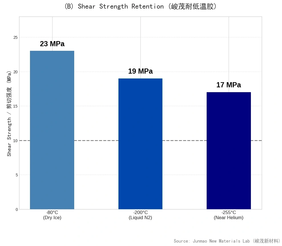
Low-temperature shear strength measured on nickel assembly bonding trials:
| Test Temperature | Shear Strength | Engineering Meaning |
|---|---|---|
| Room temperature | ≥32 MPa | Assembly and room-temperature mechanical margin |
| −80 °C | 23 MPa | Military thermal shock and high-altitude duty |
| −200 °C (liquid nitrogen zone) | 19 MPa | Strength baseline for long-term LN₂ immersion |
| −255 °C (approaching liquid helium) | 17 MPa | Minimum strength floor for cryogenic structural bonding |
Even at −255 °C the material shows no severe brittle decay, and 17 MPa covers the overwhelming majority of structural bonding requirements. The gentle slope of the shear strength curve indicates that the toughening phase still contributes to energy dissipation in the deep glassy state.
Long-term immersion has a harder number behind it: 1,000 hours of continuous liquid nitrogen immersion at −196 °C with shear strength retaining at least 95% of its value at the same temperature and no interfacial separation. Soaking is not the dominant degradation driver; cycle count is, which lines up with the micro-crack accumulation mechanism discussed in section 1.3.
Media Resistance and Chemical Inertness
After cure, SCITEO cryogenic systems are inert to a range of chemical media:
- Simulated fuel immersion for 200 hours: shear strength retained at 23 MPa
- Pure water immersion for 400 hours: shear strength retained at 22 MPa
Both results confirm that the crosslinked network is dense enough to block liquid penetration into the bond line. For LNG and liquid hydrogen duty, low permeability also means lower fluid ingress risk and stronger long-term sealing performance.
Electrical Insulation, Low Outgassing and Cleanliness
Volume resistivity across the series reaches the 10¹⁵ Ω·cm level. Under cryogenic condensation or high humidity, that insulation margin is what keeps sensor circuits safe. On the vacuum side of a cryogenic assembly, the material must additionally hold total mass loss and volatile condensable content within ASTM E595 limits, so that nothing condenses on a cold optical surface and fogs a detector. SCITEO also controls mobile ion content in this series, which keeps electrochemical migration and dendrite growth from appearing under long-term bias and condensation.
Process Execution: Surface Preparation, Step Cure and Shrinkage Control
The material sets the performance ceiling; the process decides how much of that ceiling reaches the product. SCITEO cryogenic projects typically align with the customer process team on the items below.
Surface Preparation and Interfacial Activation
Surface preparation on a cryogenic interface is not about raising room-temperature adhesion. It is about moving the failure location out of the interface and back into the adhesive: the stronger the anchoring, the more the bond line deforms internally as it cools, and the less likely the interface is to open.
In practice, metal substrates are degreased first, then roughened by grit blasting or chemical etching, with a silane coupling agent added for polar anchoring. Ceramic and glass substrates are preferably plasma activated. Composite substrates require controlled abrasion depth so reinforcing fibers are not severed.
Step Cure and Residual Stress Relief
For high-reliability assemblies, SCITEO recommends a step cure between 60 °C and 120 °C. The low-temperature stage lets the system flow, wet out and release entrained air; the high-temperature stage drives deep crosslinking; and a soak platform between them releases cure shrinkage in stages. Degree of cure is determined from DSC residual reaction enthalpy, not inferred from elapsed time.
Cure Shrinkage and Exotherm Management
The core risk in large-volume potting is the internal temperature gradient created by cure exotherm. SCITEO cryogenic potting compounds run low mixed exotherm and a low hardener fraction, with cure linear shrinkage held inside 0.2% and a 0.05% class formulation available for the most demanding positions. Projects should still calculate the core-to-surface differential from volume, and where needed split the pour or reduce the single-shot volume to keep the exotherm peak inside the process window.
Low-Temperature Verification and Acceptance
The recommended sequence is: establish the low-temperature shear baseline with ASTM D2557 and ASTM D1002 and the peel baseline with ASTM D1876; run liquid nitrogen immersion with room-temperature recovery cycles against the actual thermal profile while tracking volume resistivity and interfacial ultrasonic scanning; then run combined thermal shock and vibration testing on the assembled unit. Cycle count is derived from the service thermal profile, and room-temperature chemical acceleration models are not substituted for it.
Cryogenic Selection Quick Reference
| Duty | Typical Failure Mode | Key Criteria | SCITEO Direction |
|---|---|---|---|
| Military connector potting (−55 °C, 72 h) | Interfacial debonding, pin contact failure | Cryogenic stress relaxation, low-viscosity wetting, insulation retention | Low-Temperature High-Hardness series |
| Military sensors and deep-well instruments (−60 °C to −70 °C) | Adhesive cracking, signal drift | Thermal conduction path, low Tg, low shrinkage | Low-Temperature Thermally Conductive series |
| LNG probes and tank temperature mapping (−162 °C, long immersion) | Micro-cracks allowing fluid ingress and shorting | Cryogenic toughness, media resistance, peel strength | Extreme Cryogenic series |
| Liquid hydrogen tank and plumbing sealing (−253 °C) | Matrix damage, interfacial debonding, permeation | Low permeability, low outgassing, deep-cryogenic toughness | Extreme Cryogenic series |
| Superconducting magnet vacuum pressure impregnation (4 K class) | Insulation cracking triggering a quench | Low viscosity with long working time, cryogenic toughness, low CTE | Extreme Cryogenic series |
| Cryogen-free MRI magnet and cold-head thermal interface (4 K conduction cooling) | Thermal resistance drift, cold-head vibration transfer, insulation drop | Stable cryogenic thermal resistance, low-modulus stress buffering, stable dielectric properties | Extreme Cryogenic series |
| Quantum cryo-packaging (millikelvin class) | Outgassing contamination, rising dielectric loss, differential contraction offset | Low shrinkage, low mobile ions, low-modulus stress buffering | Extreme Cryogenic series |
| Space infrared optical payloads (40 K class) | Cure shrinkage shifting the optical path, volatile fogging | Low cure shrinkage, TML/CVCM, dimensional stability | Extreme Cryogenic series |
Conclusion: The Next Coordinates for Cryogenic Interface Materials
From a stratospheric aircraft at −55 °C to a quantum processor package at −255 °C, every step further down the temperature scale tests the same physical boundaries. Can polymer chain segments keep a limited degree of freedom? Can the interface convert contraction stress into recoverable deformation? Can the crosslinked network stay chemically inert through years of cryogenic immersion? High-field magnets for fusion energy, cryogenic interconnects for quantum computing, cryogen-free superconducting medical equipment, liquid hydrogen aviation and large-scale storage: all of them push interface materials from accessory to structural component.
As a development-driven interface materials supplier, SCITEO Advanced Materials invests in low-temperature fracture toughness, stress relaxation and low outgassing on the strength of reverse engineering from field failures. The engineering advice does not change: move reliability verification forward, complete liquid nitrogen immersion and thermal shock screening during selection, and screen out candidates with excessive low-temperature brittleness while they are still candidates, not after final assembly.
This article is SCITEO Advanced Materials original technical content; unauthorized reproduction is prohibited.
Appendix: Process & Engineering Adhesive FAQ Index
Can a cryogenic adhesive contact liquid nitrogen or liquid helium directly, and will it contaminate the cryogenic medium?
Yes, it can. A fully cured epoxy system is a three-dimensionally crosslinked thermoset network that is chemically inert in liquid nitrogen (−196 °C) and liquid helium (−269 °C): it does not dissolve, swell or leach low-molecular-weight fractions, and it does not contaminate the cryogenic medium itself. SCITEO cryogenic systems use ASTM E595 total mass loss (TML) and collected volatile condensable materials (CVCM) as the cleanliness gate, holding CVCM below 0.1% so nothing condenses as fog on a cold surface. The real engineering exposure is not media contact but cooling rate and interfacial shear stress: keep the cooling rate below roughly 3 °C per minute and hold bond line thickness between 0.05 mm and 0.15 mm at the design stage so interface stress has a release path.
If the adhesive has to resist cryogenic temperatures, why does it still need heat to cure?
Cryogenic performance depends on the cured crosslinked network, not on the cure temperature itself. Heat drives the epoxy groups and hardener to react more completely, which builds a denser network, reduces residual functional groups and lowers internal stress generated during cure. For high-reliability assemblies SCITEO recommends a step cure between 60 °C and 120 °C: the low-temperature stage lets the system flow, wet out and release entrained air, and the high-temperature stage completes deep crosslinking. The key point is that an under-cured adhesive can still hit room-temperature strength targets and then contract further and crack earlier in cryogenic service, because the chain segments were never fully locked. Degree of cure must be confirmed from DSC residual reaction enthalpy, not from elapsed cure time.
Large-volume potting cracks during cryogenic cooldown. Is shrinkage or modulus the root cause?
The two are coupled, and which one dominates shifts with volume. In small volumes, cure shrinkage and thermal shrinkage overlap and dominate; SCITEO cryogenic potting compounds hold cure linear shrinkage inside 0.2%, with a 0.05% class formulation available for the most demanding positions. As volume grows, cure exotherm creates an internal temperature gradient, so the core and the surface no longer contract in step, and the low-temperature modulus decides whether the resulting stress can be absorbed by deformation. Selection should therefore check cure shrinkage, low-temperature storage modulus and low-temperature fracture toughness together, replace fast ramps with stepped heating, and calculate whether the core-to-surface differential derived from part volume stays inside the process window.
Can the −55 °C grade and the −196 °C grade be used interchangeably?
They should not be. The two grades come from different formulation platforms. The −55 °C to −70 °C branch uses a higher filler ratio to reach 90 Shore D class hardness and 1.5 W/m·K thermal conductivity, with the objective of rigidly fixing components, suppressing vibration displacement and lowering local temperature rise through a conduction path. The −196 °C to −255 °C branch deliberately reduces filler loading to hold hardness near 60 Shore D, trading thermal conductivity for matrix elongation and low-temperature fracture toughness in order to resist the contraction shear generated by CTE mismatch. Using a high-hardness formulation at liquid nitrogen temperature raises the probability of brittle cracking, while using a low-modulus formulation in a high-vibration position gives up mechanical support.
When metals are bonded to ceramics or composites, which side of the interface fails first?
Failure usually starts where stiffness changes abruptly, or at the corner where the bond line is thickest, rather than in the weakest bulk material. Contractive displacement accumulates across the bonded area, so corners carry the highest combined shear and peel load, and a thicker bond line shrinks more and therefore generates higher peel stress at the edge. Three controls matter: degrease and mechanically roughen or plasma-activate the substrate before bonding, then add a silane coupling agent to strengthen polar anchoring; hold bond line thickness between 0.05 mm and 0.15 mm and avoid fillet build-up; and design a compliant transition or a low-modulus buffer layer so interface stress is distributed over a larger area.
How should cryogenic reliability be verified, and how many cycles are enough?
Run shear strength to ASTM D2557 and ASTM D1002, peel strength to ASTM D1876, liquid nitrogen immersion with room-temperature recovery against the actual thermal profile, and track volume resistivity to ASTM D257 throughout. Cycle count cannot be taken from a room-temperature acceleration model: the dominant cryogenic damage mechanisms are thermo-mechanical fatigue and micro-crack accumulation, which are not the same physical process as Arrhenius chemical aging, so the count has to be derived from real cooling rate, dwell time and temperature span. SCITEO recommends a 50-cycle liquid nitrogen screening run during selection, combined with interfacial ultrasonic scanning, to eliminate candidates with excessive low-temperature brittleness before they reach the assembly line.