CIS Image Sensor Packaging Adhesive: Automotive CMOS, TSV Bonding and AA Active Alignment
From cavity hermeticity and condensable-volatile control to cure-shift management in AA active alignment: the thermal-budget, cleanliness and stress boundaries behind SCITEO automotive-grade optical semiconductor adhesives, and the window that makes them producible
Abstract
Image sensor competition has moved off the pixel stack and the process node. It sits on the packaging interface now. Backside-illuminated and stacked architectures split the photodiode array from the readout logic, copper-to-copper hybrid bonding drives interconnect pitch into the micrometer range, and a third wafer folds on-package inference into the same body. Whether that roadmap reaches volume production comes down to materials: the adhesives used for wafer-level bonding, glass-lid attachment, underfill and optical fixation have to hold on three fronts at once, thermal budget, hermetic cleanliness and stress control. Miss one and yield goes with it.
CIS packaging carries more than 60% of the value in the camera supply chain, which is why the hardest engineering in optics sits here rather than in the pixel. It is not conventional IC packaging. Microlens arrays and color filters are organic systems that dislike heat and volatiles in equal measure. The cavity has to stay hermetic for the full service life, because moisture that gets in condenses on internal surfaces as the package cycles. Active alignment pins the optical axis to sub-micrometer accuracy, and any volumetric change during cure hands that precision straight back.
What follows moves through demand structure, the heat-moisture-stress boundaries, mainstream process routes, wafer-level failure chains, acceptance metrics and production control, and translates four interface classes, automotive CMOS, TSV wafer-level bonding, glass-lid cavity sealing and active-alignment fixation, into numbers that can be checked one by one against SCITEO Advanced Materials application practice.
Core Parameter Comparison
The table below puts SCITEO optical semiconductor adhesive systems alongside conventional industry practice:
| Parameter | SCITEO | Industry Norm | Test Standard |
|---|---|---|---|
| Applicable packages | WLCSP/TSV bonding, COB, Flip-Chip | COB-dominated | Not applicable |
| Material temperature window | −40 to 280 °C | 150–200 °C | TGA / long-term thermal aging |
| 260 °C reflow survival | Multiple passes, no popcorning or cracking | Delamination and cracking risk | J-STD-020 |
| Hermetic leak rate (He) | <1×10⁻⁸ atm·cc/s (internal spec) | 1×10⁻⁶ order | MIL-STD-883 Method 1014 |
| CVCM outgassing | <0.1% (optical cavity grade <0.05%) | 0.5–1% | ASTM E595 |
| CTE below Tg | 13–30 ppm/°C | 40–80 ppm/°C | TMA |
| Tg | >150 °C | 100–130 °C | DMA |
| Die shear strength | 26 MPa | 8–12 MPa | GB/T 7124 |
| Cure linear shrinkage | <0.6% | 1–3% | ISO 2577 |
| Extractable ions (Na⁺/Cl⁻) | ≤10 ppm | 30–100 ppm | IC ion chromatography |
| Volume resistivity | >10¹⁴ Ω·cm | 10¹²–10¹³ Ω·cm | ASTM D257 |
| Shear retention after TC500 | 88% | Visible decay | JESD22-A104 |
| Shear retention after 85/85, 1000 h | 75% | Visible decay | JESD22-A101 |
Where the Demand Structure Is Moving
The Value Center Has Moved to the Packaging Interface
An image sensor turns photons into electrons; packaging exists to keep that true across the entire service life. The value center has shifted down the process chain: the die only becomes a usable module after thinning, bonding, sealing, filling and optical fixation, and those steps absorb the largest single block of yield loss in the chain.
Market forecasts put mid-term CMOS image sensor revenue between roughly 30 billion and 55 billion USD, with the spread driven mostly by whether automotive and stacked-sensor growth is counted, and a compound rate somewhere in the 3% to 9% band. Asia-Pacific contributes more than 40% of revenue, and backside-illuminated and stacked BSI architectures hold the majority share while growing faster. BSI requires wafers thinned to tens of micrometers, sometimes into the teens, before flip bonding. Stacked designs require two or three wafers to be electrically joined at micrometer pitch. The module side then adds active alignment and structural fixation. Packaging materials now represent a 10-billion-USD-class slice of the wider adhesives market, with chip-level underfill and liquid molding compounds outgrowing legacy leadframe systems, and the domestic share of high-end packaging adhesives moving from under 20% to around 30%.
Four Demand Curves
Automotive imaging holds above 7% growth. Camera count per vehicle has expanded from a single reversing camera to front view, surround view, side-rear, streaming mirror and in-cabin monitoring, and mainstream forecasts now put it above eleven units per vehicle, with functional-safety targets and zero-defect goals rising in step. Global-shutter sensors grow above 7.5%, because a fast-moving object tolerates no row-by-row distortion, and in-pixel storage nodes leave no option but stacking the circuit layer onto the wafer below to free area. Short-wave infrared runs near 7.6%, imaging through fog, rain and severe glare and separating road surface from obstacles by spectral response. The fourth curve comes from robotics and embodied intelligence: the humanoid robot vision sensor segment is scaling from roughly 420 million USD toward the 2.8 billion USD class at a compound rate near 37%, with multi-camera arrays, depth cameras and event cameras compressed into one perception stack.
All four curves ask the interface for the same things. Bring the thermal budget down and the organic optical stack survives. Tighten outgassing and hermeticity and the cavity stays clean. Keep cure shift small and modulus steady and the optical path holds. Those requirements end up on one set of intrinsic material metrics.
Heat, Moisture and Stress: Three Engineering Boundaries
Thermal Budget
Color filters (CF) and microlens arrays (MLA) are organic pigment and photosensitive-resin systems. Polycarbonate and cyclo-olefin optical parts transition in the 100 to 140 °C region, flexible substrates soften earlier still, and the coating and cement layers of an IR-cut filter will not take prolonged heat either. Once heat input crosses that line and stays there, the bill comes as transmission loss, dark-current rise, yellowing and irreversible structural deformation.
The other end of the thermal budget is process-driven: a module must survive multiple 260 °C peak lead-free reflow passes, on top of rework and burn-in. Low-temperature cure and high-temperature endurance rest on different physics. The first rides on the de-blocking kinetics of a latent curing system; the second rides on the rigidity of the cured three-dimensional network. They have to be engineered separately, because no single curing agent will deliver both ends.
Hermeticity and Cleanliness
A sealed cavity is a closed gas volume, and internal pressure tracks ambient temperature. Heat it and positive pressure pushes the interface outward. Cool it and negative pressure draws external moisture inward. This breathing effect is the most common failure driver in optical packaging, and it does not pick a convenient location: the first point to give way is usually the corner with the smallest bond area and the highest stress concentration. Once hermeticity is lost, moisture condenses into droplets and staining on the sensor or the inner face of the glass lid, then combines with halide and sodium ions to drive metallization corrosion and electrochemical migration (ECM).
Cleanliness is measured on the same scale. A single micrometer-scale particle on the bond interface props open a void, breaks local hermeticity and produces a permanent optical defect, which is why bonding and lid attachment run at Class 10 or better. Cleanliness also has a chemical dimension: haze on a microlens surface is usually a contamination event first, and only shows up as an optical failure days or weeks later.
Stress and the Optical Axis
Silicon sits near 2.6 ppm/°C, organic substrates at 15 to 20 ppm/°C, aluminum structures above 20 ppm/°C, and glass lids around 3 to 4 ppm/°C. As the package cools from reflow peak to room temperature, those differences accumulate into interfacial shear stress and global warpage.
In optical packaging, warpage is never only a mechanical issue. Wafer warpage produces lithography registration error and bonding overlay error. Module warpage changes the relative position of lens and sensor. The optical-axis accuracy that active alignment worked for is redistributed by stress. Stress management therefore moves upstream into material selection; it is no longer something a failure investigation uncovers after the fact.
Process Routes and Interface Materials
Wafer-Level Packaging and TSV
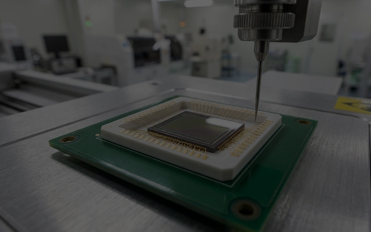
Wafer-level packaging moves bonding and sealing to wafer scale, routes connections to the backside through silicon vias, and closes a cavity with a glass lid, which suits small-to-medium formats and cost-sensitive lines. Two bottlenecks keep recurring: the CTE difference between glass and silicon creates shear stress at the bond interface, and the gas sealed inside the cavity expands during reflow.
Dam and fill is the established answer. A low-CTE dam follows the deformation of silicon and glass. The fill adhesive buffers stress and seals. Cure temperature drops into the 80 °C region to protect a completed optical stack, while the cured network still has to survive 260 °C reflow intact. SCITEO delivers the dam and fill pair for this route in a single formulation, rather than trading thermal endurance against stress margin.
Chip-on-Board
Chip-on-board (COB) attaches the bare die to the board, then adds wire bonding, bracket and lens assembly, and remains the mainstream route for high-resolution lines. Material risk concentrates in two places: volatiles and bead geometry. Volatiles that condense inside the cavity become haze. A dot that strings or slumps rewrites wire-loop height and bond-line thickness consistency on the spot.
Supply-side selection therefore favors electronic-grade purified resin at a low-outgassing grade, with CVCM held below 0.1%. Process-side control comes from thixotropic structure, so dots stay round without tails under high-speed jetting or needle dispensing and bond-line thickness stays stable. Automotive COB carries one more watch item: moving particles shed by the FPC and the dicing edge of the die. Under vibration they migrate toward the active area and eventually become a white defect that will not stay put.
Flip-Chip and Underfill
Flip-chip replaces wire bonds with bumps, raising interconnect density and signal integrity while transferring nearly all interfacial shear into the bumps themselves. Underfill has to complete a gap of a few tens of micrometers by capillary action and leave no voids behind.
Two parameters have to be verified together: Tg decides whether the adhesive is still rigid across the service window, and CTE decides whether it deforms in step with silicon and substrate. Only then comes the production ledger: capillary flow, cure shrinkage, extractable ion content. Fine-pitch designs additionally need filler particle size matched to the gap, because one oversized particle bridging a narrow passage blocks the flow path for good. Reworkability has joined the requirement set, using reversible crosslink networks that soften at moderate temperature so a repair no longer damages the substrate or neighboring parts, and molded underfill (MUF) merges filling and encapsulation into a single step to shorten the flow.
Glass-Lid Bonding and Cavity Pressure Compensation
Glass-lid bonding runs two ways: glass-on-die fixes the filter directly to the chip surface, and glass-on-housing closes a cavity on the package body. They fail the same way: cavity pressure loading as temperature changes, interfacial residual stress from cure shrinkage, and local hermetic defects caused by particles or voids.
Mature practice is easiest to read as a short sequence: B-stage pre-fixation gives the lid handling strength right after pick-and-place, so final cure no longer shifts or bleeds; a high-thixotropy bead stands upright in a narrow, tall cross-section, which turns bond-line thickness and seal width into controlled quantities; and modulus plus Tg are set to compensate cavity pressure across the service window, responding elastically instead of cracking a little more each cycle. SCITEO supplies both glass-on-die and glass-on-housing lid-attach systems, specified against narrow tall beads and B-stage pre-fixation as process prerequisites, not options.
Failure Chains in Wafer-Level Processing
TSV Etching and Metallization
A silicon via starts as a hole tens of micrometers across at a 10:1 aspect ratio, then gets filled by electroplated copper. The classic etch defect is scalloping on the sidewall, which leaves the later insulator and barrier deposition non-uniform and seeds leakage. What happens during fill, residual stress and copper grain structure, decides how those pillars expand in subsequent high-temperature steps.
Copper runs near 17 ppm/°C and silicon near 2.6 ppm/°C, a factor of almost 6.5. In high-temperature steps the copper pillar elongates axially and presses radially against the via wall, generating hoop shear stress and stress concentration in the silicon and dielectric. Once that exceeds the fracture toughness of silicon, micro-cracks extend into the dielectric and interconnect. The only lever available is low modulus plus low CTE: lower modulus flattens the stress peak, lower CTE keeps the buffer deforming closer to silicon, and fracture energy dissipates inside the interface layer. When this failure class appears, check adhesive CTE and cured modulus first, then decide whether it is a material mismatch or a process-window problem. That sequence saves a formulation change.
Copper-to-Copper Hybrid Bonding and Multi-Wafer Stacks
Once pitch moves from tens of micrometers into the micrometer range, solder volume per micro-bump becomes too small to keep shorts and opens away, and the industry turns to copper-to-copper hybrid bonding. The interface requirement is severe: post-CMP dielectric topography inside a fraction of a nanometer, copper pads recessed slightly below the dielectric, room-temperature contact through van der Waals forces, and a mid-temperature anneal that expands copper to close the recess, with alignment accuracy entering the sub-100-nanometer range.
Volume production already treats two-wafer stacking plus TSVs as routine and is moving to three-wafer stacks: a pixel wafer, a logic wafer and a circuit wafer carrying on-package inference, interconnected through face-to-face and face-to-back copper-to-copper joints at roughly 6 μm pitch. Development has pushed face-to-back pitch to 2 μm, with matching 2 μm TSV and capsule-shaped via structures, and at least one group is working toward the 1 μm class. Another wafer bonding approach uses polymer bumps for positioning and nanocellulose metal bumps for connection, completing the joint at low temperature and low stress while suppressing unbonded voids and breakage at the wafer edge.
Add layers and the bond interfaces multiply while the intermediate wafers get thinner. A single sub-100-nanometer particle or organic residue expands into a macroscopic void after anneal and opens the connection between the wafers above and below. Temporary bonding adhesives and masking materials therefore have to strip with zero residue. The chemical identity of that residue often surfaces only after anneal, in the form of a failure.
Thinning, Handling and Warpage
Stacking and miniaturization require wafers thinned below one hundred micrometers, with some lines at fifty. Rigidity drops hard, and released residual stress shows up as global bow plus local undulation: lithography registration and bonding overlay suffer together, and breakage risk rises during transport and dicing.
Thinning depends on a temporary bonding layer for mechanical support. Whether that layer's CTE and modulus match silicon sets the warpage magnitude. Residue and particles from the release step then become the next defect source. Wafer warpage, post-thinning thickness uniformity and post-release particle count usually sit on one process control chart.
Particles and Chemical Residue
Cleanliness in optical packaging runs two lines, particle and chemical. Particles come from the environment, equipment, adhesive debris and cleaning residue. Chemical residue comes from flux, photoresist, temporary bonding adhesive and cleaning solvents. Both attack the same two places: particles prop open voids at the bond interface and break local hermeticity, while chemical residue outgasses under heat and condenses on optical surfaces.
Control is a chain. Cleanroom class and positive-pressure flow fields limit particle settlement, cleaning and plasma treatment remove organic residue, and the material itself must not become a new contamination source, which is what low TML/CVCM enforces. SCITEO puts extractable ions (Na⁺/Cl⁻) at ≤10 ppm and CVCM on the same first-sample verification list, which disqualifies the wrong systems before a module is ever sealed, rather than after rework. Compliance is tightening in parallel: low-halogen and halogen-free formulations are becoming an admission condition, and full life-cycle carbon footprint is entering customer evaluation.
Metrics and Acceptance
Leak-Rate Basis and Cavity Moisture
Hermeticity cannot be judged from a single number; it must be tied to a test method and a cavity volume. MIL-STD-883 Method 1014 converts fine-leak results into an equivalent standard leak rate in air and sets limits by internal free volume: a micro-cavity at or below 0.05 cm³ lands in the 5×10⁻⁸ atm·cc/s class, 0.05 to 0.4 cm³ relaxes to 1×10⁻⁷, and only above 0.4 cm³ does it become 1×10⁻⁶. Gross-leak screening uses fluorocarbon liquid under heat to look for continuous bubbles, or fluorocarbon pressurization with gravimetric verification.
Three points deserve confirmation in review: whether the cavity volume used for conversion matches the actual package, whether helium pressurization and dwell follow the method, and whether the reported value is a measured leak rate or a converted equivalent standard leak rate. Internal moisture is measured by residual gas analysis under Method 1018 with a 5000 ppm limit, and it decides whether the cavity will condense on internal surfaces during long-term thermal cycling. For optical packages, moisture and leak rate carry equal weight, and both have to hold.
Outgassing, Water Absorption and Cavity Cleanliness
Outgassing control is a hard requirement for optical devices. ASTM E595 measures total mass loss (TML) and collected volatile condensable materials (CVCM), and the lower the CVCM, the lower the probability of contaminating the cavity and optical surfaces. Automotive and optical cavity programs hold it below 0.1%, with interior cavity grades tightening to 0.05%.
Water absorption is the parallel second line. Lower absorption means less vapor to drive popcorning at reflow peak, fewer water molecules entering the adhesive under damp heat, and a smaller transport medium for electrochemical migration. Low outgassing and low absorption have to hold in the same formulation. Trading one against the other rarely survives a combined reflow-and-damp-heat sequence.
Pairing CTE with Tg
CTE and Tg must be verified as a pair, which is the most common misjudgment at optical and advanced packaging interfaces. Take a high Tg with a CTE below Tg that does not match silicon or glass, and the interface still cracks first in thermal cycling. Take a very low CTE with a Tg below the upper service temperature, and modulus collapses the moment the adhesive enters the rubbery state, handing the entire load to the interconnect.
Practice looks like this: CTE by TMA, Tg and storage modulus by DMA, then confirmation that cure shrinkage and modulus gradient already released most interfacial stress during cure. Optical interfaces need two more readings, cure shift and moisture swelling. The first moves the optical axis; the second moves cavity dimensions and seal width. Submit the measured CTE and Tg curves as a pair and a reviewer can tell whether the margin comes from the formulation or from generous test conditions.
Serial Validation: Reflow, 85/85 and Thermal Cycling
Initial strength only proves that cure completed. Long-term reliability is set by retention after aging. Moisture sensitivity and reflow follow J-STD-020, with samples preconditioned for moisture uptake before a 260 °C peak reflow. Damp heat follows JESD22-A101 at 85 °C/85% RH with bias, and JESD22-A110 HAST provides faster screening when needed. Thermal cycling follows JESD22-A104, with automotive interfaces graded per AEC-Q100 Rev-J, where the temperature cycling test conditions are set by grade: Grade 2 is 1000 cycles from −55 to +125 °C, Grade 1 is 1000 cycles from −55 to +150 °C, and post-cycle acoustic microscopy checks the die attach and bond surfaces for delamination.
Chaining those tests with the cleaning and rework steps that follow and watching cumulative decay gets closer to real service conditions than scoring each one in isolation. On its optical CIS packaging systems, SCITEO reports 88% shear retention after 500 thermal cycles and 75% after 1000 h of 85/85, with force values and fracture location recorded together so interfacial and cohesive failure can be separated.
Cure Shift and Optical-Axis Locking
Active alignment optimizes the relative position of lens and sensor to sub-micrometer and sub-arcminute accuracy, and the adhesive has to preserve that relationship through cure and across the service window.
The cure mechanism sets the upper bound on shift. Light pre-fixation plus mid-temperature heat cure gives the adhesive handling strength first and crosslinks it while constrained, so shrinkage holds well below a purely thermal cure. Irradiation geometry matters just as much: symmetric multi-head delivery around the lens barrel prevents asymmetric shrinkage from tilting the optical axis, and shadowed regions under the barrel deserve their own degree-of-cure check, compensated with a light-thermal formulation plus an extended thermal step when needed.
The formulation then has to keep cure linear shrinkage below 0.6% and hold modulus in a window that neither creeps nor loads the optical parts. Acceptance compares MTF and optical-axis offset before and after cure and repeats it after thermal cycling. Chief ray angle (CRA) matching deserves the same check, because an adhesive shift changes the effective CRA and the relative illumination across the field follows.
Interface Selection by Application
Automotive Front and Surround View
Front-view cameras handle long-range recognition, with arrays moving beyond eight megapixels, pixel size entering the sub-micrometer range, and dynamic range above 120 dB to cover both tunnel exits and shadowed areas. LED flicker mitigation (LFM) is now a hard function. Three pressures land on the interface: structural bonding must keep cure temperature below the deformation threshold of color filters and microlens arrays, cure shrinkage must be small enough to hold the optical axis established by active alignment, and cavity cleanliness has to survive long-term aging without hazing the inner lens surface.
Surround and side-rear positions sit at the vehicle periphery, exposed to damp heat, vibration and thermal shock, where exhaust and sulfur-bearing atmospheres attack silver plating and metallization. For those, 85/85 and thermal-cycle retention describe the interface better than initial strength, and AEC-Q102 lists hydrogen sulfide (H₂S) and flowing mixed gas corrosion among the qualification items for optoelectronic devices precisely because of that outdoor duty.
In-Cabin Monitoring and Driver Monitoring
In-cabin cameras face the occupants at short working distance under complex lighting, which tightens requirements on low-light noise and dynamic range at the same time. Mounted on the dashboard, they also have to cover the high-temperature environment there.
These modules commonly bond a glass lid directly onto the die, so cavity pressure varies with temperature and the adhesive has to compensate. The floor is low modulus, low water absorption and low outgassing, with cure temperature below the color filter deformation threshold. For sealed-cavity modules in this class, SCITEO low-modulus lid-attach systems are built around lid displacement and seal-width stability across the operating temperature range.
LiDAR Receivers and SPAD Arrays
LiDAR receivers integrate single-photon avalanche diode (SPAD) arrays and ranging circuits on the same die, using stacked architecture and copper-to-copper connections to route every pixel to the processing layer below. Ranging has reached the 300 m class at 15 cm resolution, and backside-illuminated SPAD structures push photon detection efficiency above 20%.
The receiver is unusually demanding on the interface. Any scattering source raises noise, so the seal between optical window and die is stricter than for conventional imaging devices. Because operation continues under thermal shock and vibration, interface materials must hold modulus and seal width across a wide temperature range. Global-shutter and SPAD routes both fold functional safety into qualification now, and the packaging interface, as one link in the reliability chain, is expected to produce traceable aging data.
Robotics and Embodied Intelligence Vision
Embodied perception stacks bundle multi-camera arrays, depth cameras and event cameras: the arrays cover all directions, depth sensing handles spatial mapping and grasping, and event cameras capture motion at microsecond latency across more than 120 dB of dynamic range.
The difficulty here is not a single metric but quantity and consistency. One platform can distribute ten or more vision nodes, and drift at any single interface enters the calibration parameters and ends up affecting motion control. Interface materials therefore need batch-consistent cure behavior and low cure shift while meeting the narrow bead geometry that miniaturization imposes. Depth and time-of-flight (ToF) sensors are the fastest-growing categories in that stack, and SCITEO low-outgassing, low-stress systems for multi-node vision modules are released against interface consistency across every node on one platform.
AI Glasses and Wearable Imaging
Wearable imaging compresses a high-resolution sensor into millimeter-scale space while demanding long battery life. A twelve-megapixel stacked BSI sensor designed for AI glasses has already reduced package size to the five-millimeter class while retaining milliwatt-class always-on operation for environment detection and gesture recognition.
The constraints compound. The module is small and the structural parts are mostly polymers and glass, so cure temperature has to clear the softening range of optical parts and substrates. Cavity cleanliness has to be high, because any condensed volatile lands directly on the microlens surface. Assembly tolerance is minimal, so bond-line uniformity and cure shift together determine imaging consistency.
Medical Endoscopy and Industrial Machine Vision
Endoscope modules integrate sensor, illumination and optics inside a body measured in millimeters, and must survive the damp heat and chemical media of sterilization, so the interface material needs low outgassing, low water absorption and media resistance at once. Industrial machine vision cares about long-term stability and takt, and production lines will not grant a long cure window, which is what makes low-temperature fast-cure systems and pre-fixable B-stage processes worth paying for.
Both share a high cost of failure: seal failure in an endoscope is a direct medical risk, and interface drift in line-side vision produces batch-level misjudgment.
Production Control
Dispensing and Bead Geometry
Adhesive volume and placement accuracy in optical packaging are measured in micrometers, so dispense method sets geometry consistency. Dam and lid attachment suit a high-thixotropy formulation with jetting or auger dispensing, keeping the bead upright in a narrow, tall cross-section without collapse or tails. Thixotropic index and viscosity recovery time have to match line takt: recovery that is too slow builds up material in continuous dispensing, and recovery that is too fast produces stringing.
Watching dot height and area consistency in production amounts to watching bond-line thickness distribution, seal width and interfacial stress distribution at the same time.
Dual Cure and Takt
A dual-cure system separates handling strength from final strength: light pre-fixation delivers position within tens of seconds, and mid-temperature heat cure completes crosslinking and establishes final modulus and Tg. The positional relationship established by active alignment is locked during pre-fixation, so shift during heat cure stays constrained and the line does not sacrifice takt waiting for cure.
Dose and shadow zones are the parameters to watch. Where the structure blocks light, assess the degree of cure in the shadowed region and compensate with a light-thermal formulation plus extended thermal cure when needed. Partially cured areas that reach aging show up as outgassing or strength scatter.
Cleanliness and Batch Consistency
Cleanliness control is a chain. Incoming material handled under cold-chain and warm-up discipline limits moisture uptake. Dispensing and bonding at a controlled cleanroom class limit particle settlement. Cure ovens verified by temperature uniformity survey prevent degree-of-cure stratification.
Batch consistency depends on reproducible cure behavior. SCITEO puts the DSC exotherm peak and degree of cure on the release list alongside shear strength and fracture-location statistics, so process drift surfaces early. Optical modules also need hermeticity and optical performance sampling, so that mechanics, sealing and optics release on three parallel lines. That is the price of stable volume production.
CIS Packaging Adhesive Selection Reference
The table below compresses the mechanisms above into criteria a packaging or process engineer can execute directly:
| Interface | Typical Failure Mode | Primary Metrics | SCITEO Direction |
|---|---|---|---|
| TSV and copper-pillar stress buffer | Copper expansion cracking silicon, leakage drift | CTE down to 13 ppm/°C, low modulus, low cure shrinkage | Optical packaging structural adhesive (low-stress grade) |
| Wafer-level bonding and glass-lid sealing | Breathing effect exceeding leak limit, internal condensation | Leak rate <1×10⁻⁸ atm·cc/s (internal), CVCM <0.1%, low absorption | Hermetic sealant (low-outgassing grade) |
| COB die attach and wire protection | Volatile condensation haze, bead collapse affecting wire loop | CVCM <0.05%, high thixotropy, stable bond line | Low-outgassing die attach (optical clean grade) |
| Flip-chip underfill | Voids, delamination, bump fatigue | Tg >150 °C, CTE 13–30 ppm/°C, capillary flow | Chip underfill encapsulant |
| Lens barrel and filter fixation | Cure shift tilting the optical axis, MTF decay after cycling | Cure shrinkage <0.6%, dual cure, matched modulus | Optical structural adhesive (AA active-alignment grade) |
| LiDAR receiver window sealing | Interface contamination raising noise, seal width drift | Low outgassing, stable modulus across wide temperature, traceable aging data | Optical semiconductor adhesive (wide-temperature grade) |
| General automotive camera modules | Strength decay after 85/85 and cycling, ion migration | 85/85 1000 h retention, extractable ions ≤10 ppm | Optical semiconductor adhesive and formulation platform |
Conclusion
Smartphone imaging, automotive perception, industrial machine vision, embodied intelligence, wearables: every shift in optical sensor form factor passes its constraints down to the packaging interface. More stacked layers mean more bond interfaces and thinner intermediate wafers. Smaller pixels raise sensitivity to particles and chemical contamination. Higher active-alignment accuracy turns cure shift into a first-order variable. All of it lands on the same set of intrinsic material metrics: low CTE, low outgassing, low shrinkage, high hermeticity.
SCITEO Advanced Materials works on making those metrics hold in parallel. CTE in the 13 ppm/°C class plus a high-Tg backbone carries stress management. Electronic-grade purified resin brings CVCM to a level optical cavities accept. A low-shrinkage dual-cure system is matched to the cure shift active alignment allows. TML/CVCM, TMA/DMA and aging-retention data hold up to review, which is what stands behind the automotive-grade claim. Advanced TSV and hybrid-bonding structures, glass-lid sealed cavities and lens-module structural joints all find a corresponding delivery grade on the same formulation platform.
This article is SCITEO Advanced Materials original technical content; unauthorized reproduction is prohibited.
Appendix: Process & Engineering Adhesive FAQ Index
Why do glass lids pop up or delaminate after bonding, and how is this closed out in engineering terms?
Pop-up is rarely a matter of the adhesive being too weak. The cavity is a sealed gas volume: the gas contracts at low temperature and creates negative pressure, expands at high temperature and creates positive pressure, and that load crosses the adhesive into the glass-to-substrate interface. Where modulus is high, cure shrinkage is large, or the interface already carries micro-voids and particles, cyclic stress opens the weakest point, which shows up as a locally lifted lid or a delamination front. Location comes from acoustic microscopy per IPC/JEDEC J-STD-035, which reports delamination position and area fraction and separates interfacial failure from cohesive failure. On the process side, sequencing B-stage pre-fixation ahead of final cure gives the lid handling strength during assembly, so heat cure no longer shifts or bleeds it. On the formulation side, low modulus, low shrinkage and low water absorption have to arrive together, so cavity pressure converts into recoverable elastic strain instead of interfacial shear. SCITEO automotive-grade optical adhesives hold a stable narrow, tall bead, with cure linear shrinkage below 0.6%.
How does the material side buffer silicon micro-cracking caused by TSV copper expansion, and what are the quantitative limits?
The driver is a CTE gap of almost 6.5x: copper near 17 ppm/°C against silicon near 2.6 ppm/°C. After deep-via etching and copper electroplating, later high-temperature steps elongate the pillar axially and press it radially against the via wall, generating hoop shear stress and stress concentration in the silicon and dielectric. Once a micro-crack reaches the interconnect or dielectric, the failure becomes leakage and parametric drift. Low modulus plus low CTE is the only workable combination: lower modulus flattens the stress peak, lower CTE keeps the buffer deforming closer to silicon, and fracture energy dissipates inside the interface layer rather than being released locally. Pair CTE with cured modulus at selection time, and confirm cure shrinkage and Tg cover the reflow and aging conditions that follow. SCITEO formulations reach a minimum CTE of 13 ppm/°C, with TMA and DMA data available for review.
What is the chemical pathway behind microlens haze, and which metrics block it early?
Haze is organic material condensing on an optical surface. Unreacted low-molecular-weight oligomers, residual monomer and solvent carried in the adhesive escape under heat or vacuum and condense on the cooler microlens array, color filter or inner glass surface, forming an extremely thin but strongly scattering film that cuts transmission and raises dark current. Three blocking paths apply. Purify the resin system to electronic grade to reduce low-molecular-weight content at the source. Use ASTM E595 total mass loss (TML) and collected volatile condensable materials (CVCM) as the quantitative gate, with automotive and optical cavity programs held below 0.1% and interior cavity grades tightened to 0.05%. Design a stepped cure profile around the DSC exotherm peak to drive residual reaction enthalpy low, so later process steps do not release gas again.
How is cure shift controlled after AA active alignment?
Active alignment uses live image feedback to place lens and sensor optimally, and any volumetric change during cure hands that precision back. Three places can be controlled. On cure mechanism, UV or visible-light pre-fixation delivers handling strength within seconds and the heat cure that follows proceeds under constraint, with far less shift than a purely thermal cure. On irradiation geometry, symmetric multi-head sources around the lens barrel cure all deposits at once, preventing asymmetric shrinkage from tilting the optical axis; shadowed regions under the barrel need their own degree-of-cure check, compensated with a light-thermal formulation plus an extended thermal step. On formulation, cure linear shrinkage below 0.6% per ISO 2577 and modulus matched to the thermal expansion of barrel and filter holder keep cycling displacement inside optical tolerance. Acceptance compares MTF and optical-axis offset before and after cure, which reflects real risk better than adhesive strength alone.
What cavity hermeticity limit should be specified, and how should it be verified?
The limit cannot be set by rule of thumb; it has to be converted from cavity volume. MIL-STD-883 Method 1014 expresses the fine-leak limit as an equivalent standard leak rate in air and sets limits by internal free volume: a micro-cavity at or below 0.05 cm³ lands in the 5×10⁻⁸ atm·cc/s class, 0.05 to 0.4 cm³ relaxes to 1×10⁻⁷, and above 0.4 cm³ it becomes 1×10⁻⁶. Gross-leak screening uses fluorocarbon liquid for continuous bubbles or fluorocarbon pressurization with gravimetric verification. Two companion metrics have to be controlled at the same time: internal water vapor below 5000 ppm by residual gas analysis under Method 1018, otherwise even a good leak rate still condenses during thermal cycling; and overall sealing by pressure-decay method, with supplied systems verified leak-free at −30 kPa. Internal specification usually runs tighter than the standard, and bond-ring sealing can target the 1×10⁻⁸ atm·cc/s class.
Why should automotive CIS interface reliability be qualified as a coupled group under AEC-Q100 cycling conditions?
Because the failure modes interact. AEC-Q100 Rev-J sets temperature cycling test conditions by grade: Grade 2 is 1000 cycles from −55 to +125 °C and Grade 1 is 1000 cycles from −55 to +150 °C, with surface-mount devices passing moisture-sensitivity preconditioning before cycling and acoustic microscopy after cycling to check the die attach and bond surfaces for delamination. Moisture sensitivity and reflow peak temperature follow J-STD-020, and damp-heat bias is qualified at 85 °C/85% RH for 1000 h or by HAST at 130 °C/85% RH for 96 h. The real risk for interface materials shows up in the serial sequence: reflow heat creates residual stress and micro-cracks, damp-heat aging plasticizes the adhesive and lowers modulus and Tg, and thermal cycling drives the accumulated damage into the interface. First-party data on SCITEO optical CIS packaging systems show 88% shear retention after 500 thermal cycles and 75% after 1000 h of 85/85, and acceptance should run the same sample group serially rather than scoring each test in isolation.