Module Packaging Adhesives for AI Compute, Humanoid Joint and RF Modules
From 60 W/m·K extreme thermal conduction to a −255 °C to 500 °C full-temperature window: failure physics and process windows for SCITEO module-level interface materials
Abstract
Embodied AI, AI compute infrastructure and spatial computing hardware are all ramping into volume at once, and the way electronics gets assembled is changing with them. Components used to sit spread across a board; today bare dies, power devices, optical components and passive networks are pressed into a single cavity. Humanoid joint modules, RF front-end modules, optical transceiver modules and compute power modules belong to that family, and the conditions they impose on interface materials are far harsher than board-level assembly. Heat flux runs into hundreds of watts per square centimeter, the operating temperature stretches toward deep cryogenic and high-temperature extremes at the same time, and assembly tolerances close into the micron and sub-micron range. A bond line that survives that squeeze for years will not get there on one headline number.
SCITEO Advanced Materials is a development-driven interface materials supplier, and its formulation platforms are reverse-engineered from field failures: fix the module's thermal path, structural load path and chemical corrosion path first, then work back to filler grading, crosslink density and cure kinetics. The article runs through four module families — vision and sensing, power and compute, RF and communication, and extreme-temperature plus automotive-grade — and each lands on the same set of coordinates: a 4-60 W/m·K thermal matrix, a −255 °C to 500 °C portfolio, and 1,000 h+ dual-85 and 70/90 aging data.
Module-level reliability is not set by the peak datasheet value of any single material, but by whether the interface holds on thermal, mechanical and chemical boundaries at the same time. Let any one of the three give way and the most impressive device specification buys nothing.
Key Parameters at a Glance
The table sets module-level interface materials next to conventional encapsulants:
| Parameter | SCITEO | Industry Baseline | Test Standard |
|---|---|---|---|
| Thermal conductivity range | 4-60 W/m·K | 1-3 W/m·K | ASTM D5470 |
| Operating temperature range | −255 °C to +500 °C | −40 °C to +150 °C | TGA / long-term heat aging |
| Dual-85 and 70/90 aging | >1000 h | Degradation from 500 h | JEDEC JESD22-A101 |
| Structural shear strength | 20-32 MPa | 2-5 MPa | GB/T 7124 |
| Optical module CTE | 15-25 ppm/°C | >200 ppm/°C (soft gels) | TMA |
| Optical module Tg | >150 °C | <80 °C | DMA |
| CVCM | <0.1% | >1% | ASTM E595 |
| Neutral salt spray | 1,000 h, no corrosion | Corrosion from 200 h | GB/T 2423.17 |
The Physical Boundaries of Module Packaging: Why Board-Level Thinking Breaks Inside a Module
Back when components sat spread across a large board, the load on any single solder joint or bond line stayed isolated, and material selection converged on one or two numbers. Modular integration removes that premise. Quadruped robot dogs, spatial computing headsets, industrial drones, humanoid robots and AI compute power modules all take the same route: hundreds of bare dies, high-power passives and precision optical lenses squeezed into a very small cavity, interface count multiplied, and a thinner stress budget for each interface instead of a thicker one. 2.5D/3D integration and chiplet partitioning inside the package push the curve further still, splitting logic, memory and photonics into discrete dies and re-integrating them, which spreads the interface from a single board-level joint into many points inside the package.
Pressure arrives from heat flux, temperature and tolerance at once, and the three interlock. Compute and power devices now run into hundreds of watts per square centimeter, so heat has to reach the heat-spreading structure within milliseconds or junction temperature runs away. Temperature gets pulled toward both ends simultaneously, because one material family has to cover millikelvin-class cryogenic modules and the high-temperature peaks of power modules, and polymer chains behave very differently at those two extremes. Assembly tolerances are tightening as well, and optical module alignment now sits in the sub-micron range, where cure shrinkage converts directly into optical path displacement.
SCITEO concentrates its development resources on operating points where those boundaries overlap, rather than on a commodity market that only asks for baseline bond strength. The specialty polymer matrix is scoped from the application side, working backward from the thermal path, the structural load path and the chemical corrosion path to formulation parameters, with project-specific synthesis when a project calls for it instead of a longer catalogue datasheet.
Vision and Sensing Modules: Geometric Locking for AR/VR Optics and 3D Structured Light
In AR/VR headsets, VCSEL-based 3D structured-light emitters and high-end automotive sensing modules, packaging has to hold two things: the optical element must not move after active alignment and must stay put for its whole service life, and the optical path inside the sealed cavity must stay clean.
Why Low CTE and High Tg Belong Together
Once active alignment is finished, the adhesive has seconds to freeze the position. If its coefficient of thermal expansion (CTE) sits far from the silicon die or glass substrate, every subsequent thermal cycle leaves micro-stress behind, dragging the lens a few microns off axis until the image blurs. SCITEO's low-CTE optical structural adhesive grades fillers across micro and nano scales to keep CTE between 15 and 25 ppm/°C by TMA, tracking glass and silicon.
Low CTE by itself is not enough. The glass transition temperature (Tg) decides when the material leaves the glassy state; as service temperature approaches Tg, storage modulus slides and interfacial displacement plus creep start to build. SCITEO's optical structural adhesives hold Tg above 150 °C by DMA and cure into a rigid network that anchors the optical assembly to its base. Pull both curves and read them side by side rather than trusting a single point, because CTE matching drives long-term geometric stability while Tg sets the process window and the service ceiling.
The Outgassing Budget Behind Optical Fogging
Volatiles released inside a sealed module condense on lenses or VCSEL emission surfaces, and the resulting fog cannot be wiped off, which makes it a failure you cannot rework. Total mass loss (TML) and collected volatile condensable materials (CVCM) per ASTM E595 are the usual way to bound that risk, and optical or vacuum applications generally cap TML at 1% and CVCM at 0.1%. SCITEO's optical-grade encapsulation systems run on electronic-grade purification and measure CVCM below 0.1%.
Optical Waveguide Bonding and Low-Shrinkage Alignment
AR waveguides, silicon photonic coupling and optical module assembly all need an interface that passes light while holding refractive index and dimensions steady. Waveguide bonding today is dominated by UV-cure and UV-plus-thermal dual-cure systems, where the formulation targets a refractive index of 1.50 to 1.55 at the 1310 nm band, cure shrinkage within 1.2%, and item-by-item verification against the low-outgassing and damp-heat clauses of Telcordia GR-1221 and IEC 61753-1. SCITEO keeps formulations in the low-shrinkage, low-modulus stress-buffer space for waveguide bonding, lens fixation and optical engine coupling in co-packaged optics.
Power and Compute Modules: Interface Trade-offs Across Joints, Transmissions and Compute Power
High-voltage, high-dissipation output stages are where interface materials face their densest set of demands. Humanoid joint modules, drone ESC modules and rack-scale compute power modules look nothing alike, yet they solve the same problem: move heat out through a tiny cross-section while surviving years of vibration and thermal shock.
What a Joint Module Leaves You to Work With
A humanoid robot usually carries 20 to 50 actuators, one hand alone may integrate more than a dozen micro motors, and the joint actuators account for more than half of the heat the whole machine generates. Size is locked by biomimetic limits: leg and waist high-load joints generally stay within 110 mm outer diameter, elbow and shoulder joints sit between 70 and 90 mm, wrist flange diameter stays under 60 mm, and finger micro joints come in below 20 mm, while high-load joints still have to preserve a central through-hole for cable routing.
Power electronics keep migrating inward. GaN power stages push switching frequency past 100 kHz at efficiency above 99%, fieldbuses such as EtherCAT distribute commands at 4 to 32 kHz update rates, current-loop bandwidth needs to clear 5 kHz before torque response is worth discussing, and power density targets typically exceed 5 W/cm³. Stack those numbers and the thermal constraint is unambiguous: heat flux at a fingertip or inside a joint can exceed 100 W/cm², higher than quite a few compute chips, yet a joint module has no stable heat sink and heat leaves mainly by natural convection and conduction, while peak-torque duty still asks it to absorb 2 to 3 times rated torque. Thermal conduction and structural anchoring have to be carried by the same layer of material. Within SCITEO's specialty polymer matrix there is a line scoped against exactly this operating point, where the trade-off between thermal conduction and shear is settled at the formulation stage.
End Effectors, Transmission Modules and Drive-Steer Modules: The Same Constraints at a Smaller Scale
Beyond the joints, a robot carries a second family of modules that are smaller and more tightly constrained. The end effector on a dexterous hand is the clearest case: a coreless motor, a planetary or harmonic reducer, and a miniature ball screw driving tendons pack into the palm, micro motors run below 10 mm in diameter and embed directly in a finger joint, common configurations use 17 to 21 active degrees of freedom, and total hand weight stays near 400 g. Change the scale and the process changes with it: dispense volumes are measured in nanoliters, hand positioning accuracy has to reach ±0.2 mm, and a slight overflow at a finger joint can jam the neighboring joint. The tactile layer asks for more still, resolving normal force, contact location and shear at once; any creep in the bond line shows up as drift, so a low-modulus, low-moisture-uptake stress buffer holding post-cure creep within a few thousandths is the usual answer here.
Harmonic joint modules are the other mature route. A wave generator deforms the flexspline against the circular spline, engaging multiple teeth at once, so a single stage delivers ratios from 50 to 160, backlash down to around 15 arc-seconds, repeat positioning accuracy inside ±10 arc-seconds, and torsional stiffness above 20,000 Nm/rad. The seal has to withstand grease and dissimilar materials at the same time: keep ester or polyurea grease inside without swelling or being stripped by its additives, while absorbing the thermal expansion gap between a steel flexspline and an aluminum housing. A transmission module merges a frameless torque motor, reducer and dual absolute encoders into one unit, and the read window of the output encoder is acutely sensitive to cleanliness; condensable volatiles landing on the code disk turn directly into angular noise.
Drive-steer modules combine steering and traction in one unit mounted under an AGV or heavy mobile platform, where it faces washdown and salt spray for years, needs heat conducted away from busbars and windings while several hundred volts are held off, and depends on IP69K-grade encapsulation that survives 24 h continuous duty without filler settling or the potting body separating. SCITEO's combination for this class is a low-stress encapsulant plus a structural adhesive: the first holds insulation and heat transfer, the second ties stator, gearbox and housing into one rigid body, and the two layers are deliberately mismatched in coefficient of thermal expansion.
How Interfacial Thermal Resistance Couples with Shear Strength
Treating thermal conductivity as the only metric is the most common misstep here. Thermal conductivity describes the bulk material's ability to move heat, while how much heat the module actually sheds depends on interfacial thermal resistance, which in turn hangs on bond line thickness and contact integrity. Let the interface delaminate under thermal cycling or vibration, let air move into the gap, and effective conductivity drops to the conductivity of air (about 0.024 W/m·K). A high nominal rating buys nothing at that point.
That is why SCITEO always publishes thermal conductivity and shear strength together on its thermal adhesives. Rheology is engineered so the adhesive pushes entrapped micro-air out of the interface during compression bonding, and densely graded micro and nano fillers cure into a continuous conduction network: 4 to 60 W/m·K by ASTM D5470, structural shear strength of 20 to 32 MPa by GB/T 7124, and continuous high-temperature aging that clears 1,200 h at 190 °C or 300 °C. Where a heat-generating die bonds to a large metal housing, there are also high-elongation grades whose polymer chain deformation absorbs the shear strain energy from thermal shock, so the interface does not delaminate easily under sustained high-frequency vibration.
On joint-module and drone-ESC customer programs, the same situation recurs. The thermal expansion mismatch between housing and die is simply there, and under that condition the adhesive's ability to absorb strain often decides lifetime more than a higher conductivity number does. Plotting shear strength, elongation and thermal conductivity on one chart beats comparing a single conductivity value.
800 VDC Compute Power: Insulation and Heat Sharing One Layer
Rack power architecture is moving from a 48 to 54 V DC bus to 800 V high-voltage DC. The trigger is a power wall. Once a rack passes roughly 200 kW, the copper cross-section a low-voltage bus needs and the heat that comes with it both stop being workable, so the industry shifts to a high-voltage DC bus with local conversion at the rack, paired with liquid cooling loops that drive PUE toward 1.05.
Raise the voltage and interface materials pick up another job: isolate high voltage while conducting heat. Die attach and power module encapsulation must satisfy thermal conductivity, volume resistivity by ASTM D257 and partial discharge inception voltage at the same time, and hold insulation through steep switching waveforms; SiC and GaN devices drive switching edges into the nanosecond range, where the partial-discharge inception criterion is harsher than for silicon IGBTs. SCITEO supplies thermally conductive, electrically insulating systems for power modules that fold the thermal path and the isolation path into one material layer, saving both interface count and assembly steps.
RF and Communication Modules: Dielectrics, Ions and Shrinkage
Communication modules seldom fail through mechanical properties. The more common culprits are chemical impurities and dimensional drift. RF front ends, millimeter-wave antenna-in-package structures and optical transceiver modules are far more sensitive to dielectric behavior, ion content and cure shrinkage than to absolute strength.
RF Front-End Modules and Millimeter-Wave Packaging
An RF front-end module packs power amplifiers, filters, switches and low-noise amplifiers into a very small area, and millimeter-wave antenna-in-package design folds the radiating structure into the package body as well. Once water enters the polymer network, permittivity and dielectric loss rise together and insertion loss starts drifting with ambient humidity, so low moisture uptake, low dielectric constant and low loss tangent have to hold simultaneously. At the 10 GHz range, dielectric constant is usually kept below 4, loss tangent below 0.01 and moisture uptake below 0.3% before humidity drift stops eating the link budget.
Ion control is the other hard constraint. Under damp-heat bias, mobile ions at the interface migrate along the electric field and grow dendrites between fine-pitch pads, which ends as an electrochemical migration (ECM) short. SCITEO holds mobile ion content below 10 ppm. For RF modules and system-in-package assemblies that cannot take reflow temperatures, a conductive adhesive builds ohmic contact through a silver percolation network, reaching 19 MPa bond strength on gold-plated interfaces while keeping impedance low enough to preserve signal integrity margin.
Optical Modules: From 800G to 1.6T and Co-Packaged Optics
Optical interconnect turns over quickly. Per-lane rates are moving from 200 Gb/s toward 400 Gb/s, 1.6T pluggable modules are shipping at scale, co-packaged optics (CPO), near-packaged optics (NPO) and linear-drive pluggable optics (LPO) are all advancing in parallel, and co-packaged switch silicon has reached 102.4 Tb/s of switching capacity in a single chip.
Higher rates meet an upward-shifting heat flux first. DSPs, drivers and lasers sit in a tiny module volume, so the thermal interface material in that layer must hold low thermal resistance at limited bond pressure while keeping volatiles and bleed low enough not to contaminate optical parts. That is how low outgassing moved from a bonus to a mandatory check on the incoming list for optical module thermal gels. Alignment tolerance is the other boundary closing in: once the optical engine shares a package with the switch ASIC, cure shrinkage moves the coupling position directly, an overly high modulus transfers stress into the optical engine, and an overly low modulus cannot hold collimation through thermal cycling. SCITEO works that space with low-shrinkage, stress-buffering formulations for optical semiconductor packaging; its dual-cure systems measure interfacial excess loss below 0.05 dB after 2,000 h of thermal cycling, with mobile ions and condensable volatiles controlled in parallel. CPO tightens the laser's thermal boundary as well. Continuous-wave lasers are typically rated for a maximum case temperature of 85 °C, so the package relies on thermo-electric cooling to hold the laser near 55 °C, and any swing in interfacial thermal resistance converts directly into wavelength drift and output-power roll-off. Low thermal resistance and low outgassing therefore have to hold at the same time.
Extreme Temperature: From −255 °C Cryogenic to 500 °C High-Temperature Modules
Once a module leaves the temperate envelope, the thermal and mechanical limits of interface materials become direct engineering variables and leave little margin.
Cryogenic Modules: Thermal Anchoring for Quantum Computing and Superconducting Magnets
A superconducting quantum processor sits at the bottom of a dilution refrigerator at 10 to 20 mK, and cooling power at that stage is typically tens of microwatts, with only a few hundred microwatts available at 100 mK. Any extra heat path therefore eats directly into the processor's working budget. RF lines inside the refrigerator have to change materials by stage: stainless steel or cupronickel coax from room temperature down to 4 K to block the heat leak, niobium-titanium superconducting coax below 4 K to cut insertion loss, attenuators at each stage to dissipate upward thermal noise, and magnetic materials avoided end to end.
Interface materials in that architecture have to provide a repeatable low-temperature heat path and, at the same time, leave no residual stress behind from differential contraction at deep cryogenic temperatures. Most polymers lose toughness past their embrittlement point, and a small contraction mismatch is enough to pull significant tensile stress into the interface. SCITEO's cryogenic bonding and sealing systems are designed for −255 °C service, suppressing complete freezing of macromolecular chains and relieving the interfacial shear that cryogenic contraction creates.
High-Temperature Modules: Aircraft Engine Control and Downhole Measurement While Drilling
High-temperature electronics concentrate in a few settings. Aircraft engines are shifting from centralized control to a distributed architecture that pushes signal conditioning, amplification and drive modules closer to the gas path, where FADEC-class full-authority digital engine control electronics must run above 200 °C for extended periods while the gas path itself sits in the 600 °C range. Downhole measurement-while-drilling and logging-while-drilling (MWD/LWD) tools operate continuously above 175 °C, and the tubular pressure housing of a well string limits board width while offering no room for active cooling. Sensor nodes for geothermal and nuclear monitoring face much the same situation. Conventional polymers undergo main-chain scission and carbonization in those windows, and insulation resistance collapse along with pulverized adhesive is close to inevitable.
A nominal temperature rating will not tell you much. The 5% mass-loss temperature from thermogravimetric analysis (TGA), together with strength retention after long-term heat aging, is the boundary you can actually verify. SCITEO's specialty high-temperature systems use polymer phase reconstruction to deliver grades rated for continuous operation at 250 °C and 300 °C, plus formulations that break through 500 °C. They keep megohm-class insulation and structural integrity at temperature, which is what the modules above need for electrical isolation, structural fixation and sensor encapsulation.
Wide-Temperature Industrial and Defense Modules
Airborne pods, field base stations and vehicle control modules face a more complex duty cycle: a cold start in polar or high-altitude air, then a fast climb to temperature under full load. SCITEO's wide-temperature epoxy systems span −65 °C to 180 °C, staying free of brittle fracture at the cold end and holding structural anchoring at the hot end, with qualification commonly run against the high/low-temperature and thermal-shock clauses of GJB 150A.
The hard part of this window sits in the middle rather than at either end. The cold end has to keep its toughness and the hot end has to hold modulus and bond strength, and once the layer crosses Tg the modulus falls away and fixation is lost. Formulations therefore aim at a broad Tg plateau instead of chasing a single high Tg point.
Automotive-Grade and Outdoor Modules: Anti-Aging, Salt Spray and Electrochemical Migration
Automotive LiDAR, millimeter-wave radar and battery management modules are commonly expected to serve more than a decade, and they sit in a combined humidity, salt spray and thermal-cycling environment for their entire service life. An encapsulation network without enough crosslink density cannot keep water and chloride ions out; they work through free volume, hydrolyzing interfacial bonds on one path while building conductive paths between adjacent pins on another.
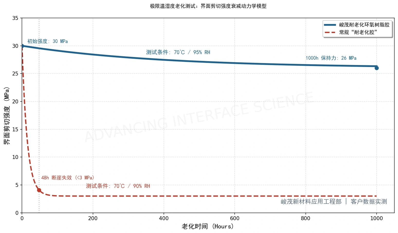
SCITEO's anti-aging systems start from two levers: crosslink density and ion content. Under dual-85 and the harsher 70/90 damp-heat regime, the systems hold pull strength and interface integrity beyond 1,000 h with no hydrolysis and no delamination (JEDEC JESD22-A101). After 1,000 h of neutral salt spray, the copper pads underneath show no corrosion (GB/T 2423.17). One link remains on the automotive qualification chain: moisture sensitivity preconditioning per IPC/JEDEC J-STD-020, layered with JEDEC JESD22-A104 temperature cycling and high-temperature storage, so the evidence chain from moisture uptake through reflow to long-term aging closes properly.
Interface Material Selection Quick Reference
The mechanisms above compress into one table you can check line by line:
| Module Type | Typical Failure Mode | Key Metrics | SCITEO Direction |
|---|---|---|---|
| AR/VR and 3D structured light | Optical axis drift, fogging | CTE 15-25 ppm/°C, Tg >150 °C, CVCM <0.1% | Low-CTE optical structural adhesive |
| Humanoid robot joint module | Interfacial delamination, conduction path collapse | 4-60 W/m·K, 20-32 MPa shear, elongation | Thermally conductive structural adhesive |
| Dexterous hand and end effector module | Adhesive overflow jams joints, tactile zero drift | Low-modulus stress buffer, low moisture uptake, low creep | Low-stress structural adhesive and thin film |
| Harmonic joint and drive-steer module | Grease bleed, encoder read noise, potting separation | Grease resistance, dissimilar-material CTE, cleanliness, IP69K encapsulation | Sealant and low-stress encapsulant |
| Compute power module | Thermal throttling, insulation degradation | 4-60 W/m·K, volume resistivity, partial discharge | Conductive and insulating integrated system |
| RF front end and mmWave package | Insertion loss drift, ECM shorts | Low moisture uptake, mobile ions at or below 10 ppm, dielectric loss | Low-ion conductive and encapsulant adhesives |
| Optical module and CPO | Coupling displacement, outgassing | Cure shrinkage, CVCM, low-modulus stress buffer | Low-shrinkage optical encapsulation |
| Cryogenic quantum and superconducting | Cold embrittlement, higher heat leak | −255 °C toughness, cryogenic conduction, non-magnetic | Cryogenic bonding and sealing adhesives |
| Aircraft engine and downhole measurement | Carbonization, insulation collapse | 250-500 °C endurance, insulation resistance | Specialty high-temperature systems |
| Automotive and outdoor | Hydrolysis, salt spray, ECM | 85/85 above 1000 h, 1,000 h salt spray, ion control | High-crosslink anti-aging systems |
Conclusion: Module-Level Reliability Is Settled at the Interface
The performance ceiling of module-level hardware ends up resting on an interface layer a few tens of microns thick. Let any one of three paths open, thermal mismatch, mechanical fatigue or damp-heat corrosion, and even the highest device specification buys nothing in terms of long-term service life.
SCITEO runs a development-driven supplier model: formulations are scoped from application-side operating conditions, test data can be verified, and the interface plan is designed alongside the customer's thermal path and structural load path. Optical locking, thermal anchoring, ion control and extreme temperature read as four product lines, but the work behind them is one thing: translating material metrics into engineering language an engineer can act on.
This article is SCITEO Advanced Materials original technical content; unauthorized reproduction is prohibited.
Appendix: Process & Engineering Adhesive FAQ Index
How does a module packaging adhesive differ from a conventional potting compound, and why can't a module-level package just reuse board-level adhesives?
The difference comes down to interface count and stress budget. On a board, components sit apart, so the load on any single solder joint or bond line stays isolated and a material can be picked against one or two numbers. Modular integration presses bare dies, power devices, optical components and passive networks into one cavity. Interface count multiplies, and at the same time heat flux climbs into the hundreds of watts per square centimeter, the temperature window stretches toward both cryogenic and high-temperature extremes, and assembly tolerances close into the micron range. The adhesive therefore has to carry thermal conduction, structural anchoring, insulation and chemical shielding simultaneously. Whichever one gives way surfaces as interfacial delamination, so the judgment has to be made on the module's multiphysics boundaries. Applying board-level single-point values will miss the real failure path.
Why must a humanoid robot joint module be evaluated on thermal conductivity and shear strength at the same time?
Because heat transfer presupposes that the interface stays in contact. Joint modules are bound by biomimetic size limits, with leg and waist joints typically kept within 110 mm outer diameter and wrist flanges under 60 mm, while still housing GaN power stages, encoders and reducers. There is no stable heat sink, so heat leaves mainly by natural convection and conduction. At the same time, a joint has to absorb 2 to 3 times rated torque for short overloads while enduring high-frequency vibration and thermal shock. If bond strength falls short, the interface delaminates under cyclic load, air gets in, and effective conductivity collapses toward that of air (about 0.024 W/m·K). No nominal rating survives that. SCITEO thermal adhesives publish both numbers together: 4-60 W/m·K thermal conductivity and 20-32 MPa structural shear strength, with high-elongation grades available to absorb shear strain energy.
What new demands do 1.6T optical modules and co-packaged optics place on interface materials?
Heat flux is climbing: DSPs, drivers and lasers are packed into a very small space, so thermal interface materials must hold low thermal resistance at limited bond pressure while keeping volatiles and bleed below the level that would contaminate optical parts. Low outgassing has therefore moved from a bonus to a mandatory check. Alignment tolerance is tightening into the sub-micron range: once the optical engine shares a package with the switch ASIC, cure shrinkage moves the coupling position directly, an overly high modulus transfers stress into the optical engine, and an overly low modulus cannot hold collimation through thermal cycling. Environmental qualification is rising too, with the low-outgassing and damp-heat clauses of Telcordia GR-1221 and IEC 61753-1 commonly used as the entry gate. SCITEO addresses this class of demand with low-shrinkage, stress-buffering formulations for optical semiconductor packaging, controlling mobile ions and condensable volatiles at the same time.
Under what conditions does a conductive adhesive replace solder in RF front-end modules and millimeter-wave packaging?
Two situations open the door. Either the process thermal budget rules out reflow, or miniaturization pushes joint size below what solder can form reliably. Pad pitch in RF front-end modules and millimeter-wave antenna-in-package structures keeps shrinking, and some system-in-package assemblies cannot survive 260 °C reflow. A conductive adhesive that builds ohmic contact through a silver percolation network can complete the interconnect inside a low-temperature window while providing 19 MPa bond strength on gold-plated interfaces. The gate is impurity control: under damp-heat bias, mobile ions at the interface migrate along the electric field and grow dendrites, which triggers electrochemical migration shorts between fine-pitch pads. SCITEO holds mobile ion content below 10 ppm and keeps cure shrinkage low so contact resistance does not drift excessively through thermal cycling.
Why do conventional epoxy systems fail in the cryogenic stages of a quantum computing dilution refrigerator?
The heat budget and the material behavior both tighten at once. The heat budget is extremely tight, because a superconducting quantum processor runs at 10 to 20 mK, where cooling power is typically only tens of microwatts, so one extra heat path directly consumes the processor's available budget. That is why RF lines inside the refrigerator step from stainless steel or cupronickel coax down to niobium-titanium superconducting coax, with magnetic materials avoided throughout. Material behavior then inverts at low temperature: most polymers lose toughness past their embrittlement point, and a small contraction mismatch is enough to pull significant tensile stress into the interface until it fractures. Cryogenic bonding and sealing systems are designed for −255 °C service, suppressing complete freezing of macromolecular chains and relieving the interfacial shear that cryogenic contraction creates.
After an automotive-grade module passes dual-85 and salt spray testing, why does the interface still need requalification in volume production?
Passing a laboratory test does not mean a stable production line. Dual-85 and neutral salt spray measure the chemical stability of a material system at a given temperature, humidity and medium condition, while production variation comes from substrate surface state, degree of cure, dispense weight and bond line thickness. Contaminated substrates change interfacial wetting behavior, incomplete cure leaves free volume channels in the crosslinked network, and dispense weight or bond line deviation redistributes stress inside the real structure. A practical approach is to run interfacial pull strength retention, void rate and mobile ion content as volume sampling items, closed-looping against post-aging data.
Why do Tg and CTE have to be read together?
They govern different failure paths. Tg marks the transition out of the glassy state: once service or process temperature approaches Tg, storage modulus falls and creep plus interfacial displacement accumulate. CTE describes dimensional response to temperature, and mismatch with adjacent materials generates shear stress at the interface. Report Tg without CTE and you miss interfacial cracking under board-level thermal cycling; report CTE without Tg and you miss modulus collapse at peak process temperature. Put both measured curves on the same temperature axis, check cure shrinkage and condensable volatiles alongside them, and you can judge whether an enlarged module structure will throw up a new stress concentration source.