High-Temp Potting Compound Selection: Phase-Transition Insulation and Extreme Sealing for 400 °C+ Sensors, Semiconductor Equipment and High-Voltage Drive Units
Semiconductor equipment chambers, SiC power modules and high-power-density drive units face carbonization and volume shrinkage above 350 °C: how SCITEO single-component phase-transition potting holds insulation, sealing and thermal conduction
Abstract
The selection logic for a high-temperature potting compound reduces to one engineering rule: whether a sensor or power module survives 400 °C-class service depends on whether thermo-oxidative degradation is suppressed, whether volume resistance holds its order of magnitude as temperature climbs, and whether the interface stays sealed through thermal cycling and pressurized steam. A nominal temperature rating decides only whether a material is allowed through the door; it does not decide service life. This article uses first-party test data from SCITEO's single-component 400 °C phase-transition potting compound to break down the two failure paths of conventional potting materials, carbonization and volume shrinkage, and turn them into criteria an engineer can execute.
Potting has moved from filling and fixing to a functional layer that must insulate, seal, conduct heat and buffer mechanical stress at the same time. Above 300 °C, conventional carbon-chain polymers cleave their backbone, degrade thermo-oxidatively and shed amorphous carbon, and the insulating medium degrades into a conductive path within tens of hours. Degradation gases leave voids inside the compound, volume shrinkage can exceed 30%, and mechanical support and hermeticity fail together.
The selection target splits into four measurable boundaries: thermal stability, read from TGA decomposition temperature and shear retention after long-term aging; insulation reliability, read from a temperature-swept volume resistance curve; sealing, read from interface integrity after boiling-water and damp-heat exposure; and thermal management, read from thermal conductivity together with sub-Tg coefficient of thermal expansion (CTE). This article covers the single-component 400 °C structural potting compound and extends to semiconductor equipment, SiC power modules, high-temperature sensors and high-voltage drives, with every figure carrying the standard it was measured against.
Core Parameter Comparison
| Parameter | SCITEO | Conventional Systems | Standard |
|---|---|---|---|
| Long-term temperature limit | 400 °C (600 °C peak) | 200-250 °C | TGA / long-term heat aging |
| Volume resistance at 300 °C/48h | 1.3×10¹⁰ Ω | drops by orders of magnitude after carbonization | GB/T 31838.2 |
| Thermal conductivity | 2.5 W/(m·K) | 0.5-1.5 W/(m·K) | ASTM D5470 |
| Tg (glass transition temperature) | ≥300 °C | 80-150 °C | DMA |
| Sub-Tg CTE | 8-25 ppm/°C (tunable) | 40-100 ppm/°C | ASTM E831 |
| Room-temperature viscosity | 3000 mPa·s | >10,000 mPa·s | Brookfield |
| Minimum penetration gap | <0.08 mm | 0.3-0.5 mm | capillary flow test |
| 100 °C boiling-water soak | no swelling, no micro-cracks | swelling, interfacial lift-off | in-house seal test |
| High-temperature volume shrinkage | <5% | >30% | ISO 2577 |
| Shear retention after 400 °C/360h | 96% | decay or embrittlement | high-temperature aging |
| Collected volatile condensable material (CVCM) | <0.01% | about 0.1% | ASTM E595 |
| Single-component design | yes, ready to use | two-component, entrapped air risk | n/a |
The 350 °C Threshold: Two Failure Paths in Conventional Potting
The 150-250 °C band no longer covers aero-turbine near-field sensing, heavy-oil inclinometers or ultra-deep logging. These duties hold service temperatures above 350 °C and add rapid thermal cycling, aggressive media and high hydrostatic pressure. Conventional modified-resin potting exposes two failure paths at that boundary, and the two reinforce each other: carbonization needs oxygen diffusion, and the voids left by shrinkage are exactly the fast path for oxygen and media into the network.
Carbonization: An Insulator Becomes a Conductive Path
The thermal stability of a carbon-chain polymer is set by main-chain bond energy and oxidation resistance. Above 300 °C, thermo-oxidative degradation accelerates exponentially; the backbone fractures, side groups are stripped off, and the residue is mainly amorphous carbon. Because carbon conducts, the potting medium that was meant to isolate signals becomes a conductive network: microvolt-level sensor output is shorted and the insulation margin at high-voltage terminals collapses. The damage accumulates with temperature and time, so a single room-temperature withstand-voltage test will not catch it. Volume resistance has to be measured at the target temperature over time.
Material design has three levers against carbonization: raise crosslink density to suppress segment mobility, introduce rigid aromatic or heterocyclic backbones to lift the decomposition temperature, and load a high volume fraction of inorganic phase to block oxygen diffusion. With any one lever missing, a compound can post an impressive nominal temperature and still fail after long-term aging, because degradation proceeds differently in oxygen-rich and oxygen-starved regions.
Volume Shrinkage and Outgassing: Structural Integrity Fails in Step
The other face of thermal degradation is outgassing. Conventional materials release small molecules at high temperature, forming visible voids inside the compound and pushing volume shrinkage above 30%. The consequences compound: voids expand and contract through every thermal cycle and become crack-initiation sites; internal precision contacts sit directly in hot pressurized gas or corrosive media; and under vacuum processing or external pressure a void provides no pressure support, so it collapses and crushes what it surrounds.
In semiconductor vacuum tools and downhole instruments, outgassing adds a contamination dimension: condensable volatiles deposit on chamber walls, probes and optical windows and produce yield loss that is hard to trace back. These duties constrain both total mass loss (TML) and collected volatile condensable material (CVCM) per ASTM E595; the screening levels long used in space and semiconductor work are TML <1.0% and CVCM <0.10%, and this SCITEO system measures CVCM below 0.01%.
Phase-Transition Reconstruction: A Material Path Around Carbonization and Shrinkage
SCITEO's application engineering group did not keep stacking heat-resistance additives onto the conventional modified-resin route. The system is built on thermally activated in-place reconstruction: a single-component 400 °C structural potting compound whose network densifies where it sits during thermal activation, using a highly crosslinked rigid backbone and a high volume fraction of inorganic phase to block oxygen diffusion and push the degradation rate beyond the service life. The compound behaves in four stages that map onto the potting process and the service profile.
Ambient Stage: Low-Viscosity Capillary Penetration with Thixotropic Control
In high-temperature MEMS and specialty connectors, contact gaps narrow to 0.27 mm, and some insulator-plate clearances fall below 0.08 mm. At room temperature the compound is a uniform high-density fluid at 3000 mPa·s. Capillary wetting carries it into micron-scale blind holes and displaces air, while moderate thixotropic resistance suppresses bleed-out at the bottom of vertical cavities. Low viscosity and high filler loading normally conflict, so SCITEO splits the formulation by process: potting and impregnation take the lower initial viscosity and a longer flow time, dispensing and blade coating take moderate thixotropy and shape retention. Both share one heat-resistant backbone platform.
The payoff from low viscosity is direct. In deep cavities and multi-layer inserts, penetration completeness decides whether an unwetted zone survives cure, and unwetted zones are where cracks start in high-temperature service. Pushing the minimum penetration gap below 0.08 mm means narrow-gap structures that once needed vacuum assistance can be potted at ambient pressure, cutting process complexity and equipment cost together.
High-Temperature Stage: In-Place Reconstruction and Carbonization-Resistant Insulation
When a device sees real service at 400 °C and even 600 °C, the specialty polymer network densifies in place under thermodynamic drive and reconstructs into a dense three-dimensional high-temperature rigid structure. The goal is to move crosslink density and inorganic-phase distribution into a state that blocks oxygen diffusion. A surface anti-oxidation coating is a temporary measure; reconstruction changes the bulk of the material.
Measured data: after 48 hours at 300 °C, volume resistance still holds at 1.3×10¹⁰ Ω per GB/T 31838.2. That order of magnitude means no continuous conductive path forms in the target temperature band, which preserves electrical margin for high-voltage ignition terminals and precision signal-processing units. In this class of material the temperature-swept volume resistance curve carries more weight than any single point, because carbonization is progressive and a passing single point does not prove long-term stability.
Sealing Stage: Boiling-Water Density and Media Resistance
High-temperature sensors rarely fail on heat alone; pressurized steam and corrosive media usually arrive with it. After reconstruction the compound is dense and delivers two capabilities.
Boiling-water resistance: a cured, potted device immersed directly in 100 °C boiling water for an extended continuous soak shows no swelling, no hydrolysis and no micro-cracking, confirming that hermeticity and interfacial adhesion still hold under combined high temperature and humidity. Once micro-cracks appear at temperature, insulation and sealing fail together, which is why this verification exposes weaknesses a temperature rating alone cannot.
Chemical resistance: against corrosive drilling mud, acidic exhaust condensate and industrial high-solvent environments, the compound stays chemically inert to acid, alkali and salt solutions and seals off the ingress path to the die. In sour reservoirs carrying H₂S and CO₂, media permeate the free volume of the network and attack metal leads, so a dense, void-free structure is a sealing requirement and a reliability requirement at the same time.
Thermal Stage: Conduction Network and Thermo-Mechanical Matching
Inside a sealed metal housing, device self-heating and external radiant heat combine and easily drive thermal drift. SCITEO embeds a thermally conductive lattice so the compound delivers 2.5 W/(m·K) per ASTM D5470 while surviving extreme temperature, moving internal heat to the metal housing and holding the internal thermal balance.
Thermal conduction has to be assessed together with thermo-mechanical matching. Measured conductivity drifts with test pressure and bond-line thickness, so potting acceptance files must fix the test condition. Tg and the sub-Tg coefficient of thermal expansion (CTE) set the interfacial stress level under thermal cycling. Matching principle comes before numbers: silicon-based sensing elements sit near 2.6 ppm/°C and copper leads near 17 ppm/°C, so set a target CTE band for the compound and check it against the bonded materials, knowing the closer the compound CTE sits to that band, the lower the interfacial shear stress. SCITEO's system holds a Tg above 300 °C, and its sub-Tg CTE is tunable between 8 and 25 ppm/°C to suit the bonded materials. Read conductivity, Tg and CTE together, and confirm they come from the same sample lot and process state.
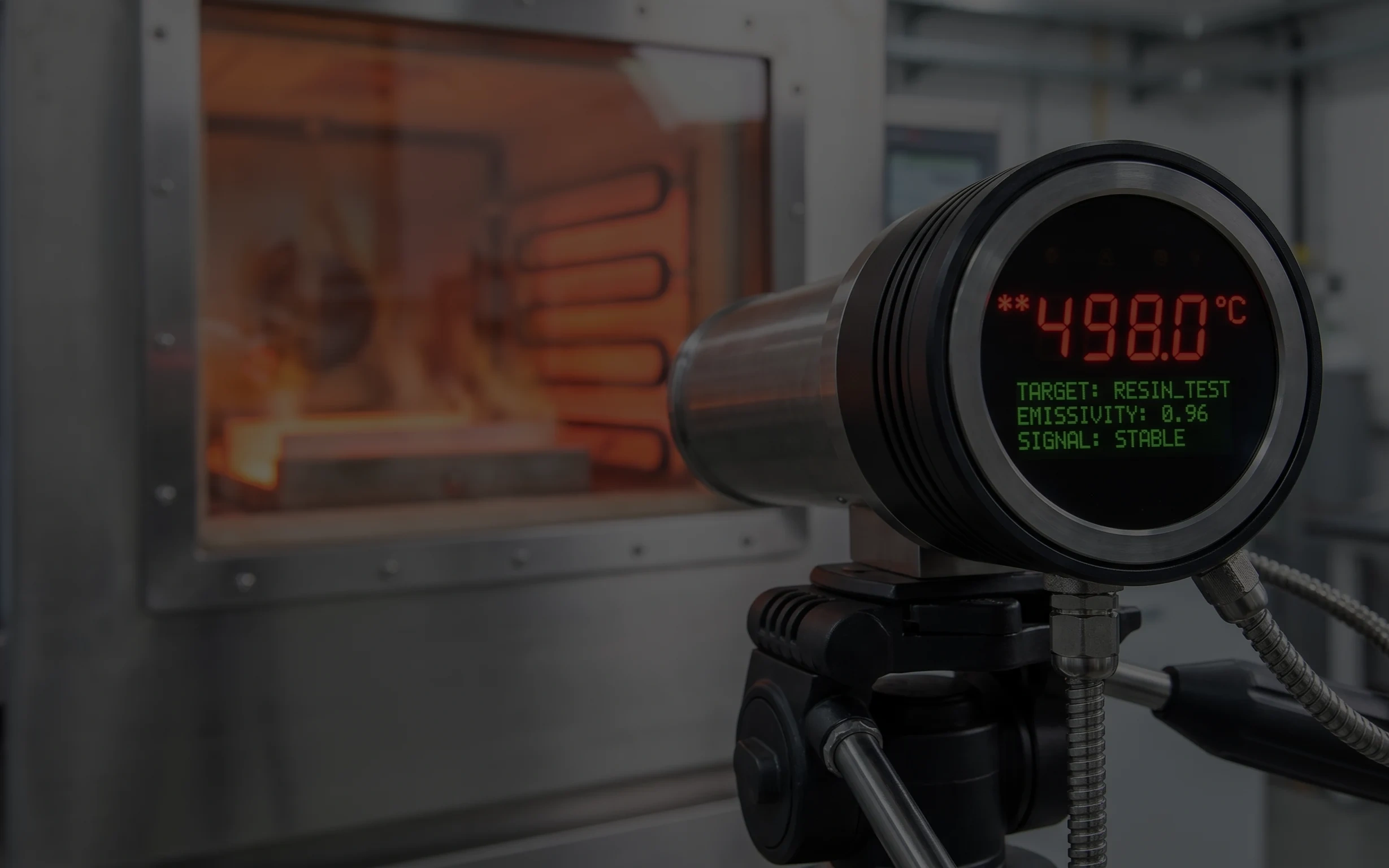
From Data to Decision: Four Evidence Sets That Hold Up
Moving selection from a datasheet to an executable criterion means gathering evidence across four failure dimensions: thermal chemistry, electrical behavior, sealing and mechanics. Skip any one of them and it returns in long-term service.
- Thermal chemistry: TGA decomposition temperature and long-term retention. The TGA curve gives the temperature band where the material begins to lose mass noticeably, the first evidence that the backbone can survive the target band. Read short-term mass loss together with retention after long-term aging: the former describes the chemical boundary, the latter the engineering boundary. SCITEO's system retains 96% shear strength after 360 hours at 400 °C, which says the crosslinked network does not degrade irreversibly over long high-temperature exposure.
- Electrical: temperature-swept volume resistance and dielectric strength. Insulation reliability cannot be judged from room-temperature volume resistance alone. Sweep volume resistance across temperature points, watch for order-of-magnitude drops, then add dielectric strength testing per ASTM D149 for breakdown voltage. High-voltage potting also needs the comparative tracking index (CTI) per IEC 60112 and partial discharge measurement per IEC 60270, because field concentration between busbars and heat sinks triggers partial discharge and tracking before outright breakdown.
- Sealing: boiling water, damp heat and pressure soak. Combine temperature, humidity and pressure. Boiling water targets hot liquid water, steady-state damp heat targets vapor diffusion, and high-pressure soaking targets permeation under hydrostatic load. Deep-well and subsea duty requires structural integrity under hydrostatic pressure in the 200 MPa class and corrosive media, where voids are the most dangerous defect: they support no pressure and they open a permeation path for media.
- Mechanics: interface fatigue under thermal cycling and shock. Temperature cycling damages an interface differently from isothermal aging, mainly through interfacial shear fatigue. Design cycles per JEDEC JESD22-A104 or run thermal shock per GJB 150A, then watch for delamination, micro-cracking and strength decay. At dissimilar-material interfaces, shear stress accumulated from CTE mismatch dominates; lowering compound CTE and cure shrinkage while raising interfacial adhesion are three parallel ways to extend cycle life.
Potting Differences Across Typical Duties
Long-term 400 °C resistance, boiling-water-class sealing and 2.5 W/(m·K) conduction together put this system into four very different duties. What they share is that the potting layer carries both insulation and sealing. What separates them is the failure driver: engines and downhole tools work against corrosive media and pressure cycling, semiconductor tools against vacuum, plasma and particles, and power modules against field concentration and CTE mismatch.
Engine and Exhaust Aftertreatment Sensing
Wideband oxygen (Lambda) and nitrogen-oxide (NOx) sensors see their service band scale with the platform: automotive wideband oxygen sensors typically run at 300-500 °C, while probes in heavy-duty diesel and marine exhaust systems run hotter and longer, all overlaid with acidic exhaust carrying sulfur and nitrogen oxides. The potting layer provides dielectric isolation and dense sealing between the metal housing and the ceramic sensing element, blocking exhaust gas and condensate from reaching the interior and shorting the sensor. Turbine exhaust gas temperature probes in aero-engines and gas turbines work under continuous high-frequency vibration and hot gas flow, where the potting layer must anchor thermocouple pins firmly against mechanical loosening and signal distortion. In this temperature band SCITEO puts interfacial adhesion and shear strength retention after thermal cycling on the required-test list.
Semiconductor Equipment and Precision Thermal Processes
Wafer-fab equipment chambers and critical components run under combined high temperature, vacuum, plasma and corrosive chemistry, a constraint set far beyond conventional electronics packaging. In dry-strip and plasma surface-treatment tools, the remote plasma source, quartz chamber and optical viewports, gas-distribution hardware and heated pedestals all face aggressive radical bombardment plus local temperature rise. The potting layer must provide long-term insulation and structural fixing while keeping outgassing and ion release low, so it neither contaminates the chamber nor generates particle defects.
Rapid thermal processing and thin-film deposition push the temperature window higher. Inside an RTP chamber, the quartz-lamp heating zone, edge ring and temperature probes see several hundred degrees, and millisecond anneal steps add transient heat-flux shock. CVD and ALD precursor lines, dual-side radiant-heated pedestals and precision showerheads work continuously from several hundred degrees up to a 1000 °C reaction environment. A showerhead face carries thousands of micro-holes whose diameter consistency and wall roughness are critical, since any particle shed becomes a wafer defect. These interfaces require the potting compound not to powder or carbonize under continuous heat while holding mobile-ion content such as Na⁺ and K⁺ at very low levels, blocking ion migration into device layers under field and humidity.
Metrology and inspection equipment adds a different constraint. Bonding layers on optical viewports, detectors and motion components inside a high-vacuum chamber must deliver outgassing-free sealing and dimensional stability, so condensable volatiles do not deposit on optical surfaces and disturb the light path. The melt-pressure sensor of a supercritical plastic extruder represents the high-temperature, high-pressure case: in the melt extrusion of specialty engineering plastics such as PEEK and PI, the probe tip withstands above 400 °C plus tens of megapascals of compressive stress, and the dense reconstructed network keeps the rear strain gauge and signal-conversion unit mechanically stable and the signal clean.
Extreme Energy Recovery and High-Temperature Electrochemistry
Measurement-while-drilling and logging-while-drilling (MWD/LWD) tools work thousands of meters downhole, where bottomhole temperature rises with depth along the geothermal gradient. Deep and geothermal wells commonly reach 175-200 °C, extreme cases approach 250 °C, and hydrostatic pressure reaches the 200 MPa class. The potting system gives the inclinometer and miniature MEMS gyroscope cavities compressive support and oil-resistant sealing while resisting corrosive drilling fluid. Because every trip is a full temperature cycle, thermal-cycle fatigue matters as much as thermal aging here. SCITEO's downhole system sets its Tg margin for a 200 °C-class bottomhole duty, and its delivery data covers interface retention after both thermal aging and trip cycling.
Solid oxide fuel cells (SOFC) and solid oxide electrolysis cells (SOEC) run their core reaction at 600-800 °C, and their near-field temperature and flow sensors work long-term near the 400 °C boundary. The potting layer must resist the thermo-mechanical fatigue of high-temperature hydrogen-oxygen reaction and keep the sensing matrix thermally balanced. Industrial boiler heat-source monitors face radiant heat from the combustion chamber and must resist powdering and carbonization over long high-temperature service.
High-Voltage Potting for SiC Power Modules
As power architecture moves to high-voltage DC, silicon carbide (SiC) power modules and solid-state transformers become core devices on the power path, with conversion stages commonly using 1200V to 3300V devices and junction temperatures reaching 175 °C and beyond. 1500 V photovoltaic inverters and energy-storage power conversion systems (PCS) push the DC bus above the kilovolt line as well and then sit in outdoor temperature and humidity swings for decades, so they share the same insulation criteria as automotive drives.
The potting layer therefore shifts from simple filling and fixing to a layer that provides high-voltage insulation, thermo-mechanical buffering and partial-discharge suppression at once, and the failure modes change with it: steep voltage transients (dv/dt) initiate discharge first at air gaps and interface defects between busbars and heat sinks, eroding insulation over time; larger temperature swings amplify CTE mismatch among the direct-bonded-copper (DBC) ceramic substrate, copper busbars and housing; and mobile ions under humidity migrate along the field and precipitate dendrites.
The gap between epoxy-resin potting and silicone-gel fill is quantifiable. Published engineering data show epoxy-resin potting systems surviving more than 3,000 thermal-shock cycles from −40 °C to 125 °C, while conventional silicone-gel fill typically survives fewer than 250. The trade-off is a tighter requirement on process cleanliness and cure schedule: once a void or unwetted zone exists, partial-discharge inception voltage (PDIV) drops noticeably.
SCITEO approaches this duty by using a highly crosslinked rigid backbone for long-term heat resistance and structural locking, a sub-Tg low CTE to buffer thermal strain, and a dense void-free structure to suppress partial-discharge inception points, then reviewing dielectric strength, CTI and partial-discharge data against the customer's actual voltage platform, switching frequency and ambient humidity. On a void-free specimen at a 1,200 V platform, PDIV reaches the 5 kV class and retains above 90% after 300 °C/48h aging; under 20 kV/μs steep pulses, formulation design holds the PDIV decay within 15%.
Integrated Potting for High-Voltage Drives and High-Power-Density Actuators
Compressing the power stage, sensing and structure into one sealed volume is the common trait of high-voltage drives and high-power-density actuators. Inverter switching produces steep pulse voltages, so the voltage distribution across windings differs completely from line-frequency duty and partial-discharge inception voltage becomes an admission criterion for the insulation system. The potting layer then does three jobs: it replaces air in turn-to-turn and layer-to-layer gaps with a thermally conductive medium to create a heat path from the end winding, buffers thermal strain with a CTE matched to copper windings and silicon steel, and stays chemically stable in oil or water cooling media.
When the power stage is embedded in a robot joint or a propulsion unit, the constraint tightens further: switching frequency is pushed into the tens to hundreds of kilohertz range for smoother torque, at the cost of a much higher volumetric heat flux in a sealed structure with no forced-air cooling, so the potting layer's thermal conductivity and thermo-mechanical stability directly set sustained output, and must be evaluated together with higher-temperature-grade magnet wire, humidity and salt spray. The adaptation logic holds the thermal boundary with a long-term heat-resistant backbone, controls stress with low CTE and low cure shrinkage, and suppresses partial discharge with a dense structure. Acceptance then closes on the potting layer itself: partial-discharge inception voltage, chemical tolerance after immersion in oil or water cooling media, and insulation retention under sustained pulse voltage.
Single-Component Thermal Cure: Process and Line Control
SCITEO's single-component system tunes its underlying activation energy to give production a single-step thermal activation route.
Surface preparation: ensure the inner wall of the metal or ceramic housing is free of grease. Plasma cleaning or grit blasting is recommended to activate micro-anchoring sites on the substrate. For dissimilar-material interfaces that must seal long-term, preparation quality directly decides whether interfacial adhesion survives thermal cycling.
Thermal activation cure: push the potted device into a constant-temperature oven, typically 150 °C/30 min, during which the specialty network completes deep crosslinking and densification. After cooling, the part is ready for 400 °C service. The specific temperature and time should follow a process instruction derived from device thermal mass and cavity depth; deep cavities and thick bond lines should extend the hold time to secure cure degree.
Process control: a short vacuum degas before potting is recommended, and the part must not contact moisture or be exposed to high humidity before full cure, to avoid introducing a moisture-absorbing layer at the interface; the ramp profile should track device thermal mass.
Back to the Potted Part Itself
The physical limits of interfacial materials often decide the service life of sensing and power systems. Crossing the 300 °C carbonization threshold while holding long-term insulation and boiling-water sealing above 400 °C tests the ultimate resistance of a polymer network to thermo-oxidative degradation; formulation tweaks alone do not settle it. At the same time, high-voltage power architectures and the high-vacuum chambers of semiconductor equipment are stacking high-voltage insulation and partial-discharge suppression onto the same potting layer. For industries going through thermal-management and high-voltage upgrades, the value of a high-temperature potting material is finally decided by whether the acceptance protocol closes on the potted part itself; a striking single figure is only an entry condition.
SCITEO Advanced Materials works at the interface layer. Across four material directions, covering temperature resistance, insulation, sealing and thermal conduction, SCITEO has built a potting matrix that spans a wide temperature range and covers both micron-scale penetration and high-viscosity filling, held together by one acceptance protocol: boiling-water-class sealing, shear retention after aging, and partial-discharge inception voltage, all three verifiable on a customer's own line.
This article is SCITEO Advanced Materials original technical content; unauthorized reproduction is prohibited.
Appendix: Process & Engineering Adhesive FAQ Index
Many potting compounds claim high-temperature resistance. How can an engineer quickly verify real extreme-condition capability?
Skip the datasheet and run a combined high-temperature insulation and boiling-water seal test. Pot the compound into a fixture with electrodes and cure it, bake it at 400 °C for 24 hours, then measure volume resistance after cooling and compare it with the room-temperature value, and finally immerse the assembly in 100 °C boiling water for 8 hours. Whitening, swelling, cracking or a resistance drop of several orders of magnitude means the network has loosened and opened moisture pathways at temperature, so it cannot survive real service. A stricter approach adds a temperature-swept volume resistance curve: a carbonization-resistant system still holds its order of magnitude near 300 °C, while a system relying on a carbon-chain backbone falls off a cliff once thermo-oxidative degradation starts. Where that cliff sits is set by main-chain bond energy and oxidation resistance, not by Tg.
Beyond convenience, what engineering advantages does a single-component design offer?
A single-component system removes the two hardest failure sources to trace: mix-ratio error and entrapped air. Two-component systems easily trap macroscopic bubbles during metering and static mixing, and a bubble is an initiation point for breakdown under high voltage, while pot life constrains the process and lot consistency depends on operator discipline. SCITEO's single-component system is a uniform high-density fluid at 3000 mPa·s, ready to use, with no partial-cure risk from a wrong ratio, and it runs reliably on fully automatic micro-dispensing, vacuum potting and pressure impregnation lines. In deep cavities and multi-layer inserts especially, cure-degree repeatability is clearly better than field-mixed two-component systems.
How does phase-transition reconstruction prevent carbonization-induced conductivity, and which data verify it?
Conventional carbon-chain polymers fail by main-chain thermo-oxidative degradation that releases amorphous carbon, and carbon conducts, so the insulating layer becomes a conductive path. Reconstruction drives in-place densification during thermal activation, using a highly crosslinked rigid backbone and a high volume fraction of inorganic phase to block oxygen diffusion and push the degradation rate beyond the service life. Verification does not rely on a nominal temperature but on three curves: the TGA decomposition temperature and mass-loss steps, the temperature-swept volume resistance, and shear strength retention after long-term high-temperature aging. This system holds 1.3×10¹⁰ Ω volume resistance after 300 °C/48h per GB/T 31838.2, and 96% shear strength retention after 400 °C/360h, covering the electrical and mechanical failure paths separately.
For SiC power modules and 800V HVDC solid-state transformers, which potting criteria should be locked first?
These interfaces stack high-voltage insulation, thermo-mechanical buffering and partial-discharge suppression in one layer, so the criteria must be evaluated as a group. Start with partial-discharge inception voltage (PDIV) and tracking resistance, per IEC 60270 and IEC 60112, because field concentration between busbars and heat sinks is the source of partial discharge and tracking. Then look at thermal-shock and temperature-cycle life: epoxy-resin potting systems withstand more than 3,000 cycles from −40 °C to 125 °C, while conventional silicone-gel fill typically survives fewer than 250. Third, require a low sub-Tg coefficient of thermal expansion (CTE) and low cure shrinkage to reduce thermo-mechanical stress on the direct-bonded-copper (DBC) ceramic substrate and copper busbars. Finally, require void-free structure and low mobile-ion content, since voids drive partial-discharge inception and mobile ions drive electrochemical migration.
For high-temperature, high-pressure electronics pods, why are Tg and hydrostatic pressure the first criteria?
Bottomhole temperature and hydrostatic pressure rise together. Conventional wells run at 100-150 °C bottomhole temperature, while deep, ultra-deep and geothermal wells commonly reach 175-200 °C, with extreme cases approaching 250 °C, and hydrostatic pressure rises from tens of megapascals to the 200 MPa class with depth. If the compound passes its glass transition temperature (Tg) at service temperature, modulus drops sharply and creep plus anchor failure follow, so Tg must exceed the maximum bottomhole temperature with margin; a 200 °C-class bottomhole duty calls for Tg above 250 °C. In sour reservoirs, H₂S and CO₂ permeate the network under high temperature and pressure and attack metal leads, so a dense void-free structure is the precondition for permeation resistance. Because each trip applies one full cycle from surface temperature to bottomhole temperature, thermal-cycle fatigue is a criterion of equal weight to thermal aging.