High-Temp Thermal Adhesive: 20-60 W/m·K TIMs for Laser Chips, IGBT/SiC and Compute Modules
SCITEO Engineering Guide: interface thermal resistance and BLT control, CTE mismatch suppression, Td5 stability at 425 °C and pump-out acceptance criteria, spanning humanoid-robot joints and 800 V HVDC liquid-cooling interfaces
Abstract
Thermal conductivity is only the entry threshold for a high-temperature thermal adhesive; interfacial thermal resistance, thermo-mechanical matching and long-term thermal stability decide service life. Drawing on SCITEO Advanced Materials first-party laboratory data, the article opens with three field cases: an automotive LiDAR module, an industrial power supply and a new-energy-vehicle power module. We took all three failed samples apart ourselves, and once the covers came off, the datasheet number fell away and the real question became what had happened at the interface in service. From there the article works through IGBT and SiC power-module cooling, high-power laser-chip attach, liquid-cooled compute chips and robot-joint drives at high temperature, and closes with selection criteria engineers can execute directly.
Power semiconductors are moving from silicon IGBT to wide-bandgap silicon carbide (SiC) and gallium nitride (GaN), pushing junction temperature limits from 150 °C toward 200 °C and above. At the same time, single-die power in AI compute platforms has crossed the kilowatt range, and liquid-cooled cold plates widen the temperature gradient between die and lid. Thermal interface materials (TIMs) have therefore moved from accessory status to structural status: they must export heat flux, absorb reciprocating shear stress from CTE mismatch, and hold insulation and ionic cleanliness under high temperature, high humidity and high-voltage bias.
SCITEO high-temperature thermal adhesives cover a continuous 2.5-60 W/m·K range: low-conductivity potting and gel grades handle cavity fill and gap conduction, while high-conductivity grades serve the thin interface in chip cooling and power-module heat dissipation, with high bond strength maintained across the line. The 37 W grade pairs 10 ppm/°C CTE with 26 MPa room-temperature shear and a 300-400 °C long-term limit, holding above 96% shear retention after 1,000 thermal cycles while suppressing both interfacial thermal resistance rise and thermo-mechanical mismatch. For higher heat flux, SCITEO builds 40 W and above thermal and conductive grades on request.
Core Parameter Comparison
The table below compares SCITEO high-temp thermal adhesives with conventional thermal adhesives:
| Parameter | SCITEO | Industry Standard | Test Method |
|---|---|---|---|
| Thermal conductivity range | 2.5-60 W/m·K | 1-3 W/m·K | ASTM D5470 |
| Long-term temperature limit | 300-400 °C | 150-200 °C | TGA / long-term heat aging |
| Ionic impurity content | below 10 ppm | above 50 ppm | IC ion chromatography |
| CTE (37 W grade) | 10 ppm/°C | above 40 ppm/°C | TMA |
| Shear strength, room temp (37 W grade) | 26 MPa | 5-10 MPa | GB/T 7124 |
| Shear retention after 1,000 thermal cycles (37 W grade) | above 96% | 60-80% | JESD22-A104 |
| Volume resistivity (60 W conductive grade) | 6×10⁻⁶ Ω·cm | 10⁻⁴ Ω·cm class | ASTM D2739 |
| Td5 (5% weight-loss temperature) | 425 °C | 310 °C | TGA |
| Thixotropic index (37 W grade) | above 3.5 | 1.2-2.0 | ASTM D2196 |
| CTE (2.5 W potting grade) | 23 ppm/°C | 50-80 ppm/°C | TMA |
Why Do Higher-Conductivity Adhesives Still Run Hot?
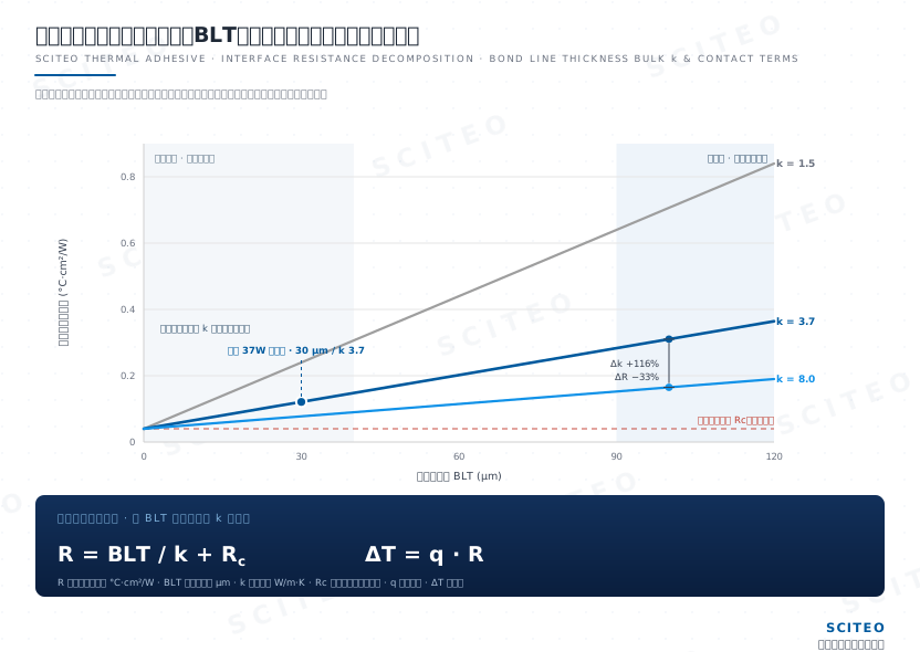
Junction temperature is governed by interfacial thermal resistance, and a single bulk conductivity figure says nothing about that layer. The most familiar scene on a production floor starts like this: an imported adhesive rated 3.0 W/m·K or higher goes into an aging test, and junction temperature still exceeds the limit, sometimes with dies detaching outright. When the sample reaches our lab, the question is almost always the same one: the conductivity spec was not low, so why is it still running hot? Teardown points to three variables that are easy to overlook:
- Bond line thickness (BLT): weak rheology control leaves the bond line too thick, and thermal resistance scales linearly with thickness.
- Interfacial contact resistance: excessive cure shrinkage causes micro-scale detachment, and phonon scattering at the interface creates a local heat-flux bottleneck.
- In-service interface degradation: pump-out, dry-out and squeeze-out reduce interface coverage over time, so thermal resistance rises non-linearly.
Across repeated ASTM D5470 measurements, we keep seeing the same thing: conductivity is highly sensitive to test pressure and bond line thickness, so the conditions behind a number matter more than the number itself. The reliable approach in selection is to read the TMA curve, cycle retention and rheology curve together; a single datasheet line does not describe how the interface behaves in service.
Case Review: CTE Mismatch Thermal Fatigue and Interfacial Micro-Cracking
The root cause of this failure is shear stress accumulated from thermal expansion mismatch: once it exceeds the adhesive yield strength, micro-cracks and delamination initiate and grow along the interface, and insufficient bond strength is only the visible symptom.
The failure appeared at the ceramic substrate bond for the heat source inside an automotive LiDAR module. After 1,000 cycles from −40 °C to 125 °C (JESD22-A104 temperature cycling), the thermal adhesive layer developed micro-cracks and thermal conductivity degraded by 40%. Our teardown routine starts with C-SAM, which showed broad delamination signals across the interface; cutting further for shear, the fracture surfaces sat mostly at the interface rather than inside the adhesive. Fracture location is the most direct evidence: the failure started at the bond line and grew into the adhesive.
Failure Mechanism
The magnitude gap alone is telling: silicon CTE is about 2.6 ppm/°C and copper about 17 ppm/°C, while conventional rigid thermal epoxy typically exceeds 40 ppm/°C and can exceed 100 ppm/°C. Stacked in one structure, the three materials contract and expand out of step. Under Hooke's law the accumulated strain converts into interfacial shear stress, and once that stress exceeds the adhesive yield strength, cohesive failure or delamination begins. If modulus is high and elongation is low, the stress has nowhere to go and micro-cracks propagate along the interface. On large-area substrates the same CTE mismatch surfaces even earlier as warpage, pre-loading residual stress into the interface.
SCITEO Solution: Core-Shell Toughening and Multimodal Filler Grading
A nano-scale core-shell rubber phase is dispersed in the epoxy matrix. When a crack initiates, rubber particles induce crazing and absorb fracture energy, arresting crack propagation without over-sacrificing modulus or heat resistance.
The SCITEO 37 W thermal adhesive holds CTE at 10 ppm/°C (TMA), lower than most advanced-packaging adhesives, delivers 26 MPa room-temperature shear strength (GB/T 7124), and retains above 96% shear strength after the same 1,000-cycle test. Power modules run two parallel reliability gates, and SCITEO qualifies one material against both: temperature cycling (TC, JESD22-A104) exercises CTE mismatch and bond-line fatigue, while power cycling (PC) exercises interface degradation under junction-temperature swing. Neither substitutes for the other. In automotive LiDAR and power module programs, SCITEO evaluates the TMA curve, the DMA modulus curve and cycle retention together, treating thermal conductivity as one input rather than the sole verdict.
Case Review: Hot-Oxidative Degradation and Powdering in Long-Term Service
Beyond the rated temperature, the decisive factor is the oxidation resistance of the polymer backbone. Short-term excursion tolerance (reflow, transient overload) and long-term continuous service temperature are two different ratings: the former can be considerably higher, and only the latter is set by oxidation resistance. A 150 °C application can still powder, because oxidative degradation accumulates over time and a single temperature threshold does not describe its progress.
Case: an industrial power module running at 150 °C triggered thermal shutdown after 2,000 hours. Teardown showed the thermal adhesive layer blackened, embrittled and powdered off. In another PCB module, the adhesive layer showed map cracking under the microscope after two reflow passes. Our practice is to run the aged layer and a retained as-delivered sample through TGA side by side: the decomposition onset of the aged layer had shifted distinctly earlier, so main-chain scission had already happened in service and powdering was simply how it surfaced.
Mechanism: classic thermal-oxidative degradation. Aromatic backbones in conventional epoxy undergo chain scission under sustained heat, and the resulting free radicals attack the main chain further until cohesion is lost. Once the layer powders, air enters the interface, the thermal path is cut and thermal resistance spikes.
SCITEO Solution: Dual Oxidation Barrier and Backbone Reconstruction
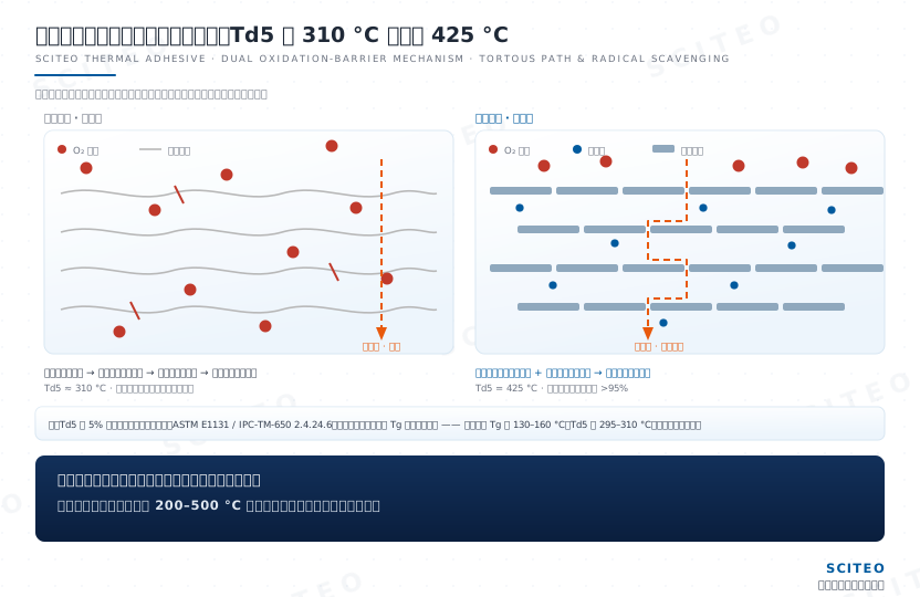
On the chemical backbone, multi-functional heat-resistant specialty epoxy with a cycloaliphatic curing agent system raises cross-linking density and with it the activation energy required for bond scission, suppressing pyrolysis at the source. Two oxidation barriers are then placed in parallel: hindered-phenol free-radical scavengers neutralize radicals generated at high temperature, while lamellar nano-fillers create a tortuous path effect that lengthens the oxygen diffusion path into the layer.
Data: in military chip customer testing, SCITEO 20 W and 37 W thermal adhesives aged continuously at 180 °C for 2,000 hours against the JESD22-A103 high-temperature storage life (HTSL) basis showed only slight surface yellowing, with no internal carbonization and no cracking. The 37 W grade retained 92% shear strength; the 20 W grade (glass transition temperature Tg 195 °C, CTE 28 ppm/°C) held 22 MPa bond strength at close to 100% retention across a −45 to 280 °C service range. TGA shows the 5% weight-loss temperature (Td5) rising from the conventional 310 °C to 425 °C. The same platform's ultra-high-temperature potting grade holds stability to the 500 °C class under short-term conditions, while long-term continuous service is still designed around a 300-400 °C window; electronic-grade packaging that needs longer high-temperature life is served by potting systems rated above 400 °C.
Automotive and telecom modules must also survive multiple J-STD-020 moisture-sensitivity and lead-free reflow shocks (260 °C peak), and automotive discrete devices are qualified against AEC-Q101 stress testing. The SCITEO 37 W grade shows no meaningful shear strength decay after repeated reflow, supporting board-level processes that require rework without introducing interfacial delamination.
Case Review: Rheology Trade-Off Between High Thermal Conductivity and Precision Dispensing
High thermal conductivity and dispensability are not mutually exclusive — filler grading and thixotropic structure design decide both, so conductivity never has to be traded away. The SCITEO application is potting and bonding for new-energy vehicle power modules, where the spec calls for above 2.0 W/m·K, dispensed through fine needles at high takt time, with no flow or slump after dispensing (shape retention).
The Physical Conflict
Thermal conduction depends on ceramic fillers such as alumina and aluminum nitride. Raising conductivity means raising filler volume loading. Beyond 60% volume fraction, inter-particle friction and agglomeration drive viscosity up exponentially, the paste loses extrudability, and automated lines cannot dispense reliably. Thin-wall designs and fast takt times amplify the conflict.
SCITEO Solution: Multimodal Particle Distribution and Thixotropic Structure
Technically this builds on an Apollonian packing model, blending fillers at 50 μm, 10 μm and 2 μm in defined ratios. Small particles fill the interstices of large particles, raising packing density and thermal pathway continuity above the percolation threshold, while the ball-bearing effect lowers internal friction.
On that graded structure, the 37 W grade reaches a thixotropic index above 3.5 (ASTM D2196): it holds shape at rest and drops in viscosity immediately under shear, matching high-takt dispensing and printing. The low-viscosity anti-pump-out grade pushes the thixotropic index past 5 to lock the interface in the low-shear region, so the platform's thixotropic index spans 3.5 to above 5 and is chosen by duty. The SCITEO 2.5 W low-viscosity thermal potting adhesive stays flowable while reaching a 250 °C rating, CTE as low as 23 ppm/°C (TMA) and 30 MPa shear strength, suitable for semiconductor module potting and filling. SCITEO production experience shows the thixotropic index is not a case of higher is better: shape retention and dispense throughput must be balanced together, and the 37 W grade value above 3.5 was fixed across multiple dispensing trials. An early route the customer tried was thinning with diluent; dispensing smoothed out, but shape retention and the thermal pathway were diluted along with the viscosity; the material could not hold up in power-module cycling, and the fix came back to particle grading.
Dispensing is only the first half of the job; the cure window is the second. The 37 W grade ships on a 150 °C/30 min thermal cure: the adhesive wets and levels during ramp, and once crosslinking completes, the bond line is locked and no downstream pressure adjustment can undo it. On a production line, dispense volume, mating pressure and ramp profile have to be tuned as one system, which is why we hand over the rheology data with the cure curve attached.
SCITEO Interface Solutions for Frontier Operating Conditions: Long-Term High-Density Heat-Flux Components
SCITEO High-Power Laser Chip Attach: Ultra-High Conductivity and Conductive Adhesives
The service limit of a high-power laser chip sits in voids and thermal resistance at the attach interface: a local void pushes heat flux into the remaining contact area and translates directly into thermal roll-off, wavelength drift and early failure.
High-power semiconductor laser chips are being pulled by two demand curves at once. Industrial pumping and laser processing keep raising the output power of laser bars, while optical interconnect pushes 1.6T modules, co-packaged optics (CPO) and near-packaged optics (NPO) into volume deployment, and external laser source (ELSFP) architectures drive high-power continuous-wave (CW) and electro-absorption modulated (EML) laser chips toward higher output power with a tighter junction-temperature window. Both curves impose the same packaging requirement: export heat efficiently across a micron-scale interface while holding void rate low, stress low and wavelength stability long-term.
The process routes therefore split by power density. Between laser bars and micro-channel coolers (MCC), AuSn hard solder and nano-silver sintering dominate in the pursuit of the lowest interfacial thermal resistance. For chip-level die attach, COS/COC attach, thermally sensitive chips, and builds that need a low-temperature process window or rework, high-thermal-conductivity conductive adhesives and sintered silver carry electrical, thermal and mechanical duties in a single layer. Void rate is the failure source both routes share, and acceptance is usually tiered by C-SAM scanning acoustic microscopy and X-ray: a local void concentrates heat flux into the remaining contact area, creating a hot spot that amplifies catastrophic optical damage (COD) risk.
SCITEO supplies production-ready materials on both routes. The 60 W/m·K conductive thermal adhesive opens electrical and thermal paths at once with 6×10⁻⁶ Ω·cm volume resistivity, matches copper heat sinks and gold plating with CTE 25 ppm/°C, and keeps the conduction network and bond strength intact after 190 °C long-term aging through a glass transition temperature (Tg) of 195 °C. The sintered silver system reaches 260 W/m·K for the highest-flux bar and COS interfaces. For drive and monitoring interfaces that require electrical isolation, SCITEO insulating thermal adhesive holds the interface flat at 13 ppm/°C CTE, preventing the insulating layer from cracking under thermal cycling.
SCITEO TIM1 Interface Solution for 800 V HVDC kW-Class Compute Liquid Cooling
Liquid cooling carries heat away from the lid while widening the die-to-lid temperature gradient, which raises TIM1 pump-out risk; interfacial stability therefore becomes a hidden cost of sustained compute output.
AI factory power and cooling are upgrading in step. On the NVIDIA Vera Rubin platform, single-GPU thermal design power reaches the 2,300 W class, rack power density reaches the 230 kW class, and the platform is designed for 100% liquid cooling. Power delivery moves from 54 V DC to 800 V HVDC and ±400 VDC to cut conversion stages and copper losses. Cold plate thermal resistance is already near 0.03 °C/W, so the bottleneck shifts from the heatsink back to the interface layers inside the package.
Under high-frequency thermal cycling, thermal grease and phase-change materials pump out, dry out and squeeze out; once interface coverage drops, thermal resistance can multiply. Room-temperature viscosity tells you nothing about pump-out resistance: the migration is driven by CTE mismatch, warpage and changes in mating pressure, so it has to be measured at the intended gap, mating pressure and cycling conditions. SCITEO grades specified for liquid-cooled conditions lock the structure with a 2.5-60 W/m·K range and 26-32 MPa-class shear strength, and the 10 ppm/°C CTE of the 37 W grade holds above 96% shear strength retention after 1,000 thermal cycles from −40 to 125 °C (TC1000), suppressing interfacial slip and delamination. Ionic content below 10 ppm keeps insulation from degrading under 85/85 (85 °C/85% RH) and high-voltage bias. For compute chips, this interface's long-term stability determines the compute a training cluster can sustain; peak cooling capacity is a one-off number. The same material platform also serves optical modules, co-packaged optics (CPO) and power bricks within liquid-cooling loops.
SCITEO Potting and Thermal System for Embodied-AI Joint Drives and SiC Double-Sided Cooling Modules
When compact cavities, continuous vibration and high-voltage insulation stack together, the answer is an integrated interface material combining thermal conduction, insulation, vibration tolerance and low stress; a thermal conductivity figure alone cannot deliver it.
Embodied AI and humanoid robots are moving from prototypes to volume delivery. Peak power per joint reaches 300-800 W, heat flux density inside the joint cavity approaches 150 W/cm², and motor windings, reducers and driver boards sit shoulder to shoulder in a small volume. The material must export heat while surviving continuous vibration and wide-temperature cycling. On the power side, SiC modules are moving to double-sided cooling (DSC), silver sintering and embedded packaging, with silicon-nitride AMB (active metal brazing) ceramic substrates progressively replacing conventional DBC substrates, and junction temperatures pushing above 200 °C, which raises the bar on temperature limits and low thermal resistance.
For this scenario, the SCITEO 2.5-11 W/m·K thermal potting compound and gel series delivers three capabilities: high volume resistivity and dielectric withstand for electrical isolation in high-voltage driver modules; CTE 23 ppm/°C and 30 MPa shear strength in the potting grade to keep stress low across wide-temperature cycling and avoid interface fatigue from combined vibration and thermal load; and tunable viscosity and thixotropy for cavity filling, gap conduction and automated dispensing. The same platform also serves power conversion systems (PCS) for energy storage, photovoltaic inverters and low-altitude electric propulsion, where rising power density, constrained space and non-negotiable reliability are common denominators.
What Keeps the Interface Intact in Service
On paper, selection comes down to this: thermal conductivity clears the entry threshold first, and what actually decides life is whether the interface holds in service. Ionic cleanliness, the TMA curve, cycle retention and thixotropic structure are the four evidence sets we put side by side. Miss one and the failure shows up during ramp. High-power laser chips and optical-module light sources, IGBT/SiC power modules, kW-class compute-chip liquid cooling, embodied-AI joint drives and low-altitude electric propulsion will keep raising both heat flux and shear stress at the bond line. SCITEO Advanced Materials meets those duty cycles with a 2.5-60 W/m·K thermal matrix, 260 W/m·K sintered-silver conduction paths and low-CTE structural locking, measurable and repeatable batch to batch, and holds that evidence discipline as frontier processes introduce new constraints.
This article is SCITEO Advanced Materials original technical content; unauthorized reproduction is prohibited.
Appendix: Process & Engineering Adhesive FAQ Index
Why does some adhesive erode sensitive components such as MEMS after cure?
The core issue is ionic content control. Residual chloride (Cl⁻) and sodium (Na⁺) ions in low-grade adhesives drive electrochemical migration and insulation degradation under high temperature, high humidity and high-voltage bias. Next to MEMS and optical devices, trace ion migration is enough to cause leakage and drift. Every SCITEO electronic-grade product is purified through ion-exchange resins, with ionic content below 10 ppm, meeting semiconductor packaging standards and validated under 85/85 (85 °C/85% RH) plus high-temperature bias.
Epoxy thermal adhesive versus silicone thermal adhesive: how do I choose?
Look at the engineering constraint set. Choose epoxy when you need high bond strength (the SCITEO 37 W grade delivers 26 MPa room-temperature shear), oil and solvent resistance, rigid support and structural locking. Choose silicone when you need elastic stress release, reworkability and moderate bond strength. In IGBT and SiC power modules where pump-out and CTE mismatch occur together, epoxy with low CTE (10 ppm/°C) and high modulus has the advantage. In compact cavities under sustained vibration, silicone's low modulus absorbs deformation.
Why do thermal grease and thermal pads dry out and pump out at high temperature, and when do I have to move to a thermal adhesive?
Start by separating what each format actually solves. Thermal grease has no structural strength: the carrier oil bleeds and oxidizes under sustained heat, the layer sees cyclic shear migration, and it degrades through pump-out, dry-out and squeeze-out, so thermal resistance multiplies over service time and pump-out can appear within hundreds to thousands of thermal cycles. Thermal pads hold contact through mounting pressure and compression rebound, but rebound fades after long high-temperature compression, and a minimum thickness floor keeps them out of micron-scale bond lines. Where the duty calls for high temperature, a thin bond line and structural locking at the same time, a curable structural thermal adhesive is the format that locks BLT, CTE and bond strength together; where the interface is reworkable, pressure is ample and the temperature rise is mild, grease remains the reasonable lower-cost choice.
Why does a cured thermal adhesive feel tacky on the surface?
Usually oxygen inhibition or a wrong mix ratio. Two-component adhesives must be blended through a static mixer, otherwise locally under-cured material leaves a tacky skin, and the air-exposed surface can remain under-cured through oxygen inhibition. SCITEO single-component thermal adhesives use latent curing agents that trigger crosslinking instantly at temperature, eliminating mix-ratio error by design; the cured surface is firm and dense, ready for the next process step.
For high-power laser chip attach such as laser bars and COS, why can neither a standard thermal adhesive nor a hard solder alone do the job?
Both extremes expose a weakness. A standard thermal adhesive has low conductivity and limited temperature margin, so at the kilowatt-per-square-centimeter heat flux of a laser bar it rolls off thermally within a short service window. A pure hard solder achieves very low interfacial thermal resistance, but its process window is narrow, it is void-sensitive and difficult to rework, and CTE mismatch transfers stress into the laser facet, amplifying catastrophic optical damage (COD) risk. Practice therefore layers by power density: micro-channel cooler (MCC) interfaces favor AuSn eutectic or nano-silver sintering for the lowest thermal resistance, while chip-level COS/COC attach and thermally sensitive or reworkable builds use high-thermal-conductivity conductive adhesives or semi-sintered silver to satisfy electrical, thermal and low-stress requirements together. SCITEO 60 W/m·K conductive thermal adhesive meets electrical, heat-flux and stress constraints at once with 6×10⁻⁶ Ω·cm volume resistivity and CTE 25 ppm/°C, while the sintered silver system reaches 260 W/m·K for the highest-flux bar and COS interfaces.
As SiC junction temperature approaches 200 °C and liquid cooling widens the interface gradient, why must CTE and modulus be evaluated together?
Because the failure mode shifts from insufficient heat conduction to interface degradation. Higher junction temperature combined with the liquid-cooling gradient imposes higher-frequency, larger-amplitude shear stress on the interface layer. If CTE is high or modulus is low, the interface slips, delaminates or pumps out after thousands of cycles, and thermal resistance climbs. SCITEO reads the TMA curve (CTE), DMA modulus curve and post-cycle shear retention on the same material: the 37 W grade delivers 10 ppm/°C CTE, 26 MPa room-temperature shear and above 96% retention after 1,000 thermal cycles, balancing thermal path continuity and structural locking across the 300-400 °C long-term range.
How do I select a thermal adhesive for IGBT modules, and why qualify temperature cycling and power cycling separately?
Lock three hard numbers before comparing conductivity. CTE must sit close to copper and the ceramic substrate; the 37 W grade measures 10 ppm/°C by TMA. Room-temperature shear needs structural margin at 26 MPa (GB/T 7124). Shear retention after 1,000 thermal cycles must stay above 96% (JESD22-A104), a post-cycle figure rather than a fresh value. Temperature cycling (TC) exposes bond-line fatigue accumulated from CTE mismatch; power cycling (PC) exposes interface degradation under junction-temperature swing. Their heat-source distribution and time scale differ, so neither substitutes for the other, and production qualification normally runs both in parallel. An interface that fails either gate shows up early in service as rising thermal resistance.