Anti-Aging Epoxy Reliability: Damp-Heat Aging, Thermal Cycling, and Acceleration Models
SCITEO anti-aging epoxy engineering guide: failure mechanisms across six dominant aging pathways, 85/85, HAST, thermal-cycling and salt-spray test criteria, and the bounds of life-model extrapolation — spanning −255 °C to 400 °C
Executive Summary
Microelectronics packaging, automotive electronics, defense electronics, and new-energy equipment all ask the same thing of an adhesive: that it still carry load and hold insulation margin at the end of the product's service life. Aging is the irreversible decay of the adhesive bulk or the bond line under coupled temperature, humidity, chemical, and mechanical stress. It advances along several parallel paths — diffusion, plasticization, hydrolysis, oxidation, interfacial disbondment — and those paths carry different activation energies, so which one dominates shifts with the service condition. This article breaks the failure chain into six mechanism classes, maps the standards and failure criteria behind 85/85 damp heat, HAST, PCT, thermal cycling, and salt spray, and sets out what Arrhenius, Hallberg-Peck, and Coffin-Manson each do and where each stops being valid. SCITEO's high-crosslink-density epoxy systems span −255 °C to 400 °C, with humidity, salt-spray, and chemical-media validation written to military, automotive, and semiconductor-grade requirements.
Initial strength describes the material on the day it ships. The reliability boundary is drawn by three things together: failure mechanism, accelerated test, and life model.
Adhesive Aging Mechanisms: Six Dominant Failure Paths
Service environments rarely apply a single stress. Aging proceeds along three paths at once — cohesive degradation of the bulk, disbondment at the bond line, and functional failure where substrate and adhesive couple. Those paths respond differently to heat and moisture, so the useful order of work is: decompose the failure chain first, then decide what to test and how.
Moisture Ingress: Diffusion, Plasticization, and Interfacial Disbondment
Water enters the cured epoxy network by Fickian diffusion. Uptake rises roughly with the square root of time before leveling toward saturation; where water is retained at filler interfaces, dual-Fick or Langmuir-corrected models fit the measured curve far better. A typical structural epoxy saturates at 2% to 5% uptake at 100% RH, held as both free and bound water. Plasticization depresses the glass transition temperature — a working figure is 1 °C to 2 °C of Tg loss per percent of absorbed moisture. Where the Tg margin is thin, wet Tg closes on the service temperature and modulus collapse arrives together with accelerated creep. Sorption also drives hygroscopic swelling; smaller than thermal expansion, it still contributes independent interfacial shear under constant-temperature, high-humidity duty.
The more damaging path is the interface. Metal oxides have a high affinity for water. Moisture diffuses inward from the bond edge and progressively displaces the bonds between adhesive and oxide, advancing a disbondment front from the perimeter inward at a diffusion-controlled rate that tracks the square root of time. The process is irreversible — drying does not restore strength — so short immersion data materially overstate long-term damp-heat performance. Under acidic or alkaline interfacial conditions, ester linkages in the epoxy network hydrolyze, and falling molecular weight compounds the loss of crosslink density; the measurable result is a steady decay in shear strength.
Moisture uptake can be attacked on two fronts: raise crosslink density and hydrophobic resin content to cut saturation uptake, and use silane coupling plus surface treatment to strengthen interfacial bonding so the disbondment front advances more slowly. SCITEO's anti-aging epoxy systems are built on that pair of levers. They hold above 90% shear strength after 1,000 hours at 85 °C/85%RH with no cracking or disbondment under extended validation, and keep sealing and insulation function past 60 days of continuous water immersion — margin for subsea sensors and outdoor precision instruments.
Thermal Aging and Thermo-Oxidative Degradation: Scission, Oxidation, Mass Loss
Heat accelerates every chemical reaction. It attacks epoxy through two channels. Physically, passing Tg collapses modulus, accelerates creep, and locks in unrecoverable plastic deformation. Chemically, main-chain scission, side-group detachment, and mass loss take over; quantifying them means TGA onset temperature, the 5% weight-loss temperature (Td5), and char yield.
Oxygen escalates thermal aging into thermo-oxidative degradation. Published comparisons are stark: 10 hours at 260 °C in nitrogen costs a conventional high-temperature adhesive almost nothing, while 1 hour at the same temperature in air drives strength close to zero. The difference is radical chain oxidation — oxygen forms peroxy radicals on the polymer backbone, which cleave chains and advance the embrittled layer inward. High-temperature selection therefore requires both numbers, inert-atmosphere and oxidative-atmosphere endurance; quoting only one is a common source of misjudgment.
SCITEO's high-crosslink-density systems raise aromatic content in the backbone and pair it with hindered-phenol antioxidants that interrupt radical chain propagation, pushing the thermo-oxidative window outward. The data set covers 195 °C for 1,500 hours, 90% shear retention after 500 hours at 230 °C, and 400 °C for 500 hours — directly usable for cross-temperature design in high-power devices and defense electronics.
Thermal Cycling and Thermomechanical Stress: CTE Mismatch and Fatigue Accumulation
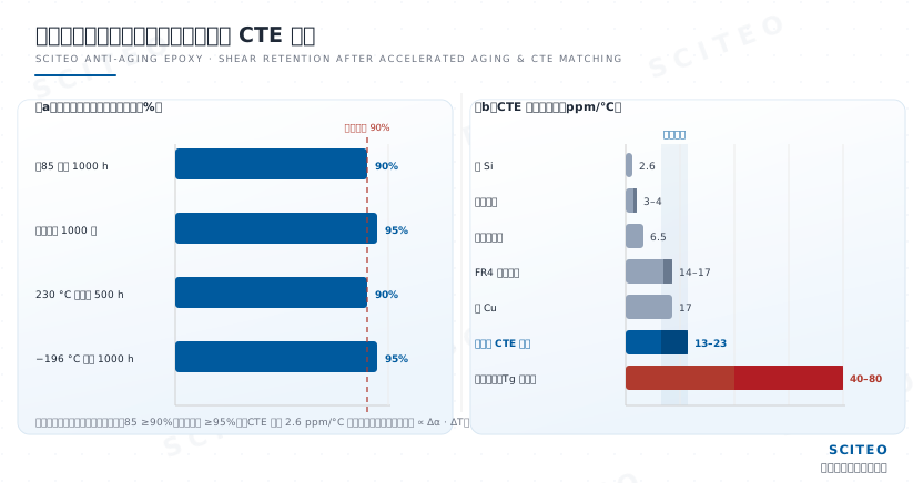
Adhesive layers in semiconductor packaging and power electronics live under cyclic thermal stress. Silicon sits near 2.6 ppm/°C, copper leads near 17 ppm/°C, glass-fiber substrates at 14 to 17 ppm/°C in plane, while a conventional epoxy below Tg runs 40 to 80 ppm/°C. The adhesive and the substrate therefore contract out of phase, generating cyclic interfacial shear strain; damage accumulates with every cycle until it is released as delamination, disbondment, or cohesive cracking. JEDEC JESD22-A104F.01 defines the −40 °C to 125 °C cycle used to quantify exactly that.
Thermal stress is controlled by three things: lower the adhesive's CTE, cut cure shrinkage, and leave toughness margin at the interface. SCITEO's low-CTE epoxy systems use nano-spherical filler grading to bring CTE down to 13 to 23 ppm/°C, hold cure shrinkage below 0.06%, and absorb each temperature swing's cyclic strain through flexible segments, keeping the fatigue accumulation rate low. After 1,000 cycles between −40 °C and 125 °C, shear retention still measures 95%. Low CTE, high Tg margin, and low shrinkage only pay off together, and only in the residual strength measured after cycling.
Oxygen and Ozone: Surface Embrittlement and Radical Chain Reactions
At ambient temperature oxygen damages crosslinked polymers slowly; add light or heat and the rate climbs exponentially. Oxidation starts at the outer surface, where peroxy radicals attack the polymer chain and produce crazing, chalking, loss of gloss, and discoloration, with the embrittled layer working inward. Industrial practice rarely treats oxygen as a single variable — thermo-oxidative and photo-oxidative combinations are how the assessment is actually run.
Light and Radiation: Photochemical Scission
Ultraviolet photons carry enough energy to break C-C and C-H bonds in epoxy and polyurethane systems. Pristine polymers have a low photochemical quantum yield, but catalyst residues, impurities, and photosensitive additives in a formulated adhesive act as sensitization centers, amplifying photo-oxidation under heat and oxygen into yellowing, cracking, and mechanical decay. Adhesives for outdoor transparent parts need a weathering-resistant formulation and a UV stabilizer package. In that class of application, SCITEO designs the stabilizer package together with a low-sorption network, so photo-oxidation and moisture plasticization are suppressed by the same formulation.
Chemical Media Attack: Swelling, Dissolution, and Functional Failure
Acids, alkalis, salt solutions, industrial lubricants, solvents, and corrosive gases swell, dissolve, or erode the adhesive. Swelling brings volume expansion and strength loss, and the secondary failures follow: lost hermeticity, degraded insulation resistance, conductivity drift in conductive adhesives. In potted and sealed structures, media ingress also shifts dielectric constant and volume resistivity. SCITEO's anti-aging epoxy systems are molecularly engineered for the media they meet, resisting hundreds of fluids including antifreeze, jet fuel, engine oil, acetone, isopropanol, and PCB flux. After 30 days in 5% salt spray and in oil immersion, shear strength holds at 28 MPa with no decay; after 30 days in isopropanol and acetone, bond strength remains above 24 MPa.
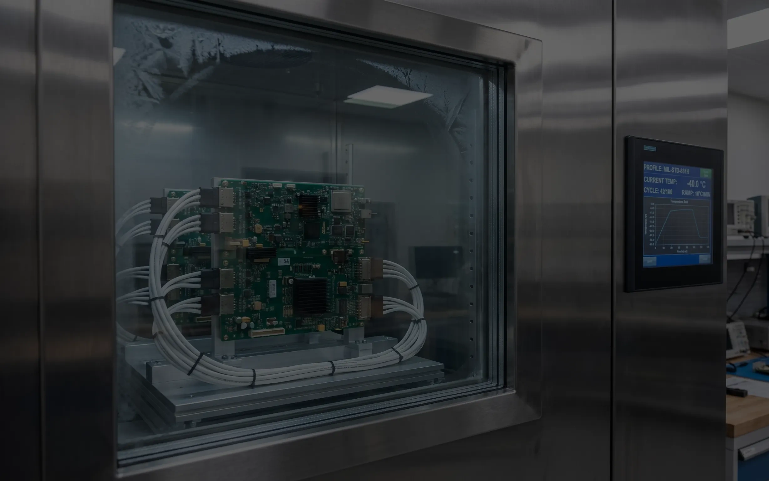
Accelerated Aging Test Standards and Failure Criteria
Nobody can wait for a material to age naturally. The industry compresses failure time with accelerated stress and then extrapolates service life with a physical-chemical model. Test design comes first: define what counts as failure — for example, shear strength no lower than 25 MPa after 85/85 with retention no lower than 90% — and then match stress level and duration. A test that measures initial properties without a failure criterion produces a set of numbers, not a life statement.
85/85 Damp Heat (THB)
The 85 °C/85%RH steady-state temperature-humidity-bias test is the benchmark for microelectronics and photovoltaics. JEDEC JESD22-A101 specifies 1,000 hours under bias; AEC-Q100 Rev-J makes it mandatory for automotive devices (Grade 1); IEC 61215 requires 1,000 hours at 85/85 for PV modules. The Chinese counterpart is GB/T 2423.50 (steady damp heat, Test Cy), with the base method in IEC 60068-2-78:2025 (Test Cab) — Edition 3 revised the chamber requirements, the severities and dew-point temperatures, and converted the temperature tolerance to limits. 85/85 probes more than damp-heat resistance: it also covers electrochemical corrosion, ionic migration, and insulation-resistance decay.
HAST and PCT: Pressure-Accelerated
HAST stacks pressure on top of temperature and humidity, using saturated vapor pressure to drive moisture into the package faster. JEDEC JESD22-A110E defines two conditions: 130 °C/85%RH at 230 kPa (about 33.3 psia) under bias for 96 hours, and 110 °C/85%RH at 122 kPa for 264 hours. The standard also states the equivalence: for parts that reach moisture equilibrium within 24 hours, 96 hours at 130 °C/85%RH equals 1,000 hours at 85 °C/85%RH. The unbiased variant, JESD22-A118 (uHAST), is aimed more at exposing interfacial delamination and moisture-induced cracking. PCT (JESD22-A102) runs 121 °C/100%RH at roughly 2 atm of saturated steam for extreme hermeticity screening. Acceleration factors reach 100x to 1,000x; both tests complement 85/85 rather than replace it.
One boundary is easy to miss. JESD22-A110E itself notes that absorbed moisture lowers the effective Tg of plastic packaging materials, so once HAST stress temperature exceeds wet Tg, the test can activate failure mechanisms that differ from atmospheric 85/85. Before using HAST data to extrapolate 85/85 life, confirm both sit in the same mechanism regime. SCITEO's pressure-accelerated data ships with wet Tg and mechanism attribution recorded, so the valid range of any extrapolation can be re-checked.
Thermal Cycling and Thermal Shock
JESD22-A104F.01 covers single-, dual-, and triple-chamber cycling in a gaseous medium, applies to components and solder interconnects, and explicitly excludes the fast-ramp thermal shock produced by liquid-coupled chambers. MIL-STD-883 and GJB 548 define separate thermal shock methods for transient stress under extreme temperature differentials. Thermal cycling damages the adhesive mainly through cumulative fatigue, with cycle count and ramp rate setting the damage budget together. Thermal shock reads strain rate; thermal cycling reads strain time and accumulation. Neither substitutes for the other.
Salt Spray and Media Tolerance
The neutral salt spray test in ISO 9227:2022 / GB/T 10125-2021 (5% NaCl) covers marine and automotive environments, with recommended exposure periods at 240, 480, and 720 hours. GJB 150.11A runs 35 °C, 5% NaCl, 24 hours spray plus 24 hours dry per cycle, and is the entry condition for military equipment. The GJB 150 series spans high temperature, low temperature, damp heat, and salt spray in combination; GJB 150.4A low temperature and GJB 150.9A damp heat together bound wide-temperature reliability validation. One clarification is owed here: the GJB 150.4A method framework reaches into the −70 °C class, and liquid-nitrogen-range cryogenic duty is a project-level extension whose profile has to be agreed separately.
Accelerated Aging Test Matrix
| Test | Typical Condition | Standard | Failure Focus |
|---|---|---|---|
| 85/85 damp heat | 85 °C/85%RH, 1,000 h | JESD22-A101 / GB/T 2423.50 | Shear retention, insulation resistance, ionic migration |
| bHAST | 130 °C/85%RH at 230 kPa, 96 h | JESD22-A110E | Moisture ingress, cohesive decay, electrochemical corrosion |
| uHAST | 130 °C/85%RH, 96 h | JESD22-A118 | Interfacial delamination, moisture-induced cracking |
| PCT | 121 °C/100%RH, ~2 atm | JESD22-A102 | Hermeticity, interfacial disbondment |
| Thermal cycling | −40 °C to 125 °C, 1,000 cycles | JESD22-A104F.01 | CTE matching, stress fatigue, delamination |
| High-temperature storage | 150 °C to 195 °C, over 1,000 h | JESD22-A103 | Thermo-oxidative decay, strength loss |
| Cryogenic storage | −70 °C to −196 °C, 1,000 h | GJB 150.4A (method framework); LN2 range is a project-level extension | Low-temperature embrittlement, microcrack accumulation |
| Neutral salt spray | 5% NaCl, 240 to 720 h | ISO 9227:2022 / GB/T 10125-2021 | Interface corrosion, adhesion decay |
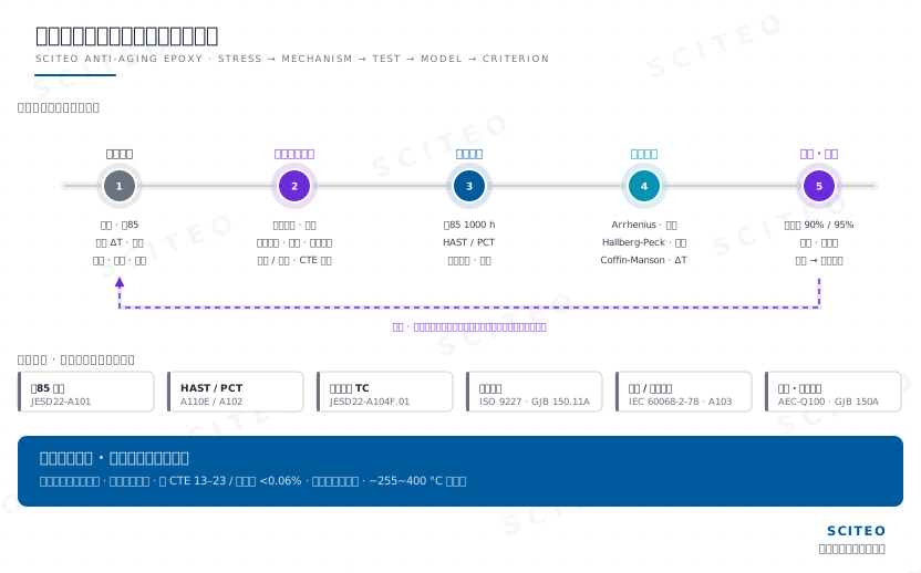
Lifetime Models: Acceleration Factors and Extrapolation Limits
An accelerated test returns a failure time at one specific stress. Service life needs a model. Temperature, humidity, voltage, and temperature swing each accelerate differently, and each has its own model:
| Model | Core Acceleration Factor | Where It Applies, and What to Watch |
|---|---|---|
| Arrhenius | Temperature | The foundational electronics model. Failure rate varies exponentially with temperature; the governing parameter is apparent activation energy Ea (typically 0.6 to 1.0 eV). Single-temperature acceleration only — humidity is excluded. |
| Arrhenius with a humidity term | Temperature + humidity | Adds a relative-humidity exponent to the Arrhenius base. Suited to non-condensing combined environments and routinely used for consumer electronics and structural adhesives in temperate humidity zones. |
| Hallberg-Peck | Temperature and humidity coupled | Semiconductor-grade model carrying both temperature and relative humidity. Humidity exponent n runs 2.5 to 3; Peck's calibration gives n ≈ 2.7 and Ea ≈ 0.79 eV for aluminum corrosion. Quantifies acceleration under 85/85 and HAST. |
| Inverse power law / voltage term | Voltage (optionally coupled to temperature and humidity) | Adds a voltage power term V^-m on top of the temperature-humidity model. Used for electrochemical migration (m ≈ 1 to 2) and dielectric breakdown mechanisms; biased THB and HAST have to include it. |
| Coffin-Manson / Norris-Landzberg | Temperature swing ΔT (with cycle frequency and peak temperature) | The dedicated thermal-cycling model: cycles to failure vary inversely with a power of ΔT (roughly 1.9 to 2.5 for lead-free solder). Norris-Landzberg additionally carries cycle frequency and peak temperature, and is the mainstream route for extrapolating solder-joint and adhesive-layer thermal-fatigue life. |
Hallberg-Peck takes the form tf = A·(RH)^-n·exp(Ea/kT), where RH is relative humidity, n the humidity acceleration exponent, Ea the activation energy, k the Boltzmann constant, and T absolute temperature. Extrapolating from 85 °C/85%RH to a 25 °C/50%RH service environment yields acceleration factors in the 100x to 1,000x range — the quantitative basis for equating 1,000 hours at 85/85 with years in the field. Measured retention trends for SCITEO's anti-aging epoxy systems under 85/85 and HAST track the model's extrapolation window, so the measured data and the theory corroborate each other.
Three rules govern extrapolation. First, a model holds only within one failure mechanism: moisture plasticization and hydrolytic chain scission carry different Ea values, and mixing the parameters yields an optimistic life. Second, stress temperature must not cross the material's wet Tg or its decomposition knee — otherwise the failure the test accelerates will not reproduce in service. Third, the extrapolation endpoint needs measured data behind it; a curve fitted through a few temperature points is a reference value only. The same applies to thermal cycling: Coffin-Manson's exponent and Norris-Landzberg's frequency term both assume one fatigue mechanism, and once ΔT is stretched beyond the real duty cycle, the predicted cycle count drifts away from actual life.
Verification ends at the fracture surface. The failure locus after a shear test has to be recorded alongside the strength number. Failure inside the adhesive layer (cohesive) says the bulk has degraded; failure at the interface (adhesive) points to broken interfacial bonds or interface aging; mixed fracture indicates compound damage. For a given system, the failure mode typically migrates from cohesive to interfacial as aging proceeds, and where that migration curve sits says more about the protection design than any single strength value.
Anti-Aging Epoxy Selection Criteria
| Criterion | Engineering Practice | SCITEO Counterpart |
|---|---|---|
| Tg margin | Dry Tg at least 20 °C above the maximum service temperature; verify wet Tg as well | High-Tg epoxy systems |
| CTE | CTE below Tg matched to the substrate; below 30 ppm/°C preferred | CTE 13 to 23 ppm/°C series |
| Thermal stability | TGA onset temperature, Td5, and long-term endurance data | 195 °C/1,500 h, 400 °C/500 h |
| Shear retention | No less than 90% after 85/85 and 95% after 1,000 thermal cycles | ≥90% after 1,000 h at 85/85; ≥95% after 1,000 thermal cycles |
| Water uptake and wet Tg | Lower saturation uptake is better; assess together with wet Tg | High-crosslink-density hydrophobic formulations |
| Media tolerance | Immersion or salt-spray validation against the actual media | 28 MPa after 30 days in 5% salt spray |
| Cryogenic toughness | No brittle cracking or disbondment at LN2 temperature; stable low-temperature modulus | Cryogenic series spanning −255 °C to −70 °C |
| Failure mode | Post-aging fracture migration from cohesive to interfacial stays controlled and the ratio is traceable | Fracture-locus records delivered with strength data |
Typical Applications and Process Pain Points
Mechanisms and standards eventually have to land on a real duty cycle. Both application areas below share one trait: passing in the lab is only the ticket in; the real threshold appears in the production process window and in long-term system-level service.
Automotive Electronics and Power Modules
What automotive customers hit most often is not insufficient initial strength — it is "passes in the lab, fails early in the vehicle." A vehicle is designed around 15 years, yet a module cycles from −40 °C to above 125 °C year after year, and the junction-temperature swing from power cycling puts adhesive and solder joints under shear simultaneously. Once the interface delaminates, rising thermal resistance pushes device temperature up, which accelerates aging further: a positive feedback loop.
The process side concentrates its own difficulties. The window for narrow-gap filling is tight, and a small deviation in dispense path or substrate preheat traps bubbles; incompletely cleaned flux residue destroys interfacial wetting; an overly steep cure ramp locks shrinkage stress straight into fragile interconnect structures. None of this shows up at the sample stage — it converges during production ramp and in the field. What SCITEO delivers on automotive programs includes residual strength and fracture-locus records after cycling, not only an initial-strength report from the sample stage.
Sensor Packaging and Low-Temperature Service
Sensors are a precision business, and residual packaging stress converts directly into a customer's after-sales cost. Zero-point drift, sensitivity loss, and data scatter after batch calibration tend to surface only at system calibration. Piezoresistive pressure sensors and accelerometers measure micro-displacement to begin with, so a stiff adhesive layer or excessive cure shrinkage transfers stress onto the sensing structure. The conflict sits right there: low modulus to release stress, yet enough bond strength and media resistance; low-temperature cure to protect an already-completed calibration, yet adequate crosslink density and batch consistency.
Low-temperature service pushes that conflict harder. Defense and aerospace sensors cold-start year-round in deep-cryogenic ranges such as −70 °C, where the material's modulus behavior decides whether the signal can be trusted — which is the fit target for SCITEO's cryogenic epoxy series. For extreme cases such as superconducting magnets and quantum devices, the formulation floor extends to −255 °C. The anti-aging, cryogenic, and low-stress lines share one formulation platform, and SCITEO folds the customer's process window into the design so the material runs stable on their line.
Conclusion: The Reliability Floor
Aging takes countless forms across duty cycles, yet the criteria converge on one set of questions: can the failure mechanism be identified, can the accelerated test be reproduced, does the life extrapolation have defined bounds, and can the measured data be traced. When all four hold, a material becomes credible in an engineering sense.
A datasheet describes the state at the moment of delivery; reliability describes behavior across the entire service life. That distance cannot be closed by initial strength — only by understanding the failure mechanism and by validation that reproduces. Moisture-heat, thermal-cycling, thermo-oxidative, and chemical-media stress behavior is turned into predictable, traceable verification quantities inside SCITEO's engineering system, rather than unknowns left for the field to discover.
This article is SCITEO Advanced Materials original technical content; unauthorized reproduction is prohibited.
Appendix: Process & Engineering Adhesive FAQ Index
How do I determine whether an adhesive has already aged and failed?
At the micro level, aging appears as polymer chain scission, crosslink-density decline, or an advancing interfacial disbondment front; macroscopically it shows as surface gloss loss, yellowing, cracking, hardness change (embrittlement or tackiness), and irreversible shear-strength decay. The engineering criterion requires both: shear strength no lower than 25 MPa after aging and retention no lower than 90%; insulation applications should also monitor leakage current and insulation-resistance drift. Record the fracture surface alongside the strength number — migration from cohesive failure inside the adhesive to interfacial failure means the protection design has started to give way.
Why do semiconductor packaging adhesives require extremely low CTE?
Silicon CTE is only about 2.6 ppm/°C, while conventional epoxies below Tg run 40 to 80 ppm/°C. Under thermal cycling the mismatch generates cyclic interfacial shear stress that accumulates into bond-wire fracture, die delamination, or underfill cracking. SCITEO's low-CTE epoxy systems (CTE 13 to 23 ppm/°C) paired with cure shrinkage below 0.06% keep thermal stress inside what the interface can carry.
What should I consider when selecting adhesives for continuous operation above 200 °C?
Never rely on ambient strength alone. Verify Tg margin, TGA decomposition onset, and long-term thermal-aging data, and distinguish inert-atmosphere from oxidative-atmosphere endurance. Conventional epoxies lose mechanical properties significantly above 150 °C; for continuous service above 200 °C, specify high-Tg modified epoxy systems and demand continuous high-temperature data such as SCITEO's 195 °C/1,500-hour and 400 °C/500-hour validations.
What is the difference between 85/85 and HAST, and how do I choose?
85/85 (85 °C/85%RH, 1,000 hours) is the steady-state temperature-humidity-bias test covering damp-heat resistance, electrochemical corrosion, and ionic migration per JESD22-A101. HAST (130 °C/85%RH at 230 kPa, 96 hours) adds pressure to accelerate moisture ingress per JESD22-A110E; for parts that reach moisture equilibrium within 24 hours it is equivalent to 1,000 hours of 85/85, and a milder 110 °C/264-hour condition is also defined. Run 85/85 first for routine qualification; use HAST or PCT (121 °C/100%RH) when rapid exposure of sealing and penetration defects is required. Note that once HAST stress temperature exceeds the material's wet Tg, the test can activate mechanisms that differ from atmospheric 85/85 — confirm both sit in the same regime before extrapolating.
What is shear-strength retention, and why does it matter more than initial strength for aging resistance?
Retention is the ratio of post-aging shear strength to initial shear strength. Initial strength reflects the process window and formulation strength, while retention reflects the damage-accumulation rate during aging; only the combination tells you whether the material can hold structural integrity over the design life. SCITEO's anti-aging epoxy systems start at roughly 30 MPa shear strength, retain above 90% after 1,000 hours at 85/85, and still hold above 24 MPa after 720 hours at 155 °C, leaving ample design margin.
How do I extrapolate 1,000 thermal cycles to a 15-year vehicle life?
Thermal cycling does not follow Arrhenius; it follows fatigue. Coffin-Manson relates cycles to failure to a power of the temperature swing ΔT, with an exponent of roughly 1.9 to 2.5 for lead-free solder. Norris-Landzberg adds cycle frequency and peak temperature on top of that, and is the mainstream route for solder-joint and adhesive-layer thermal-fatigue life. Converting bench data at −40 °C to 125 °C with two cycles per day to a vehicle duty cycle with a smaller ΔT typically lands in the single-digit to low-double-digit acceleration range, so 1,000 bench cycles represent several thousand real temperature excursions. Once ΔT is pushed beyond the real duty cycle the model breaks down, so extrapolation has to be bounded by measured residual strength and fracture-mode data.
Do epoxy adhesives embrittle and fail in cryogenic service?
Conventional epoxies embrittle sharply once chain segments freeze in the liquid-nitrogen range, and microcracks accumulate through thermal cycling until disbondment occurs. Cryogenic selection therefore hinges on low-temperature fracture toughness and low-modulus design. SCITEO's cryogenic epoxy series endures down to −255 °C, remaining modulus-stable and free of brittle cracking in the liquid-nitrogen range, with up to 95% strength retention after 1,000 hours of −196 °C storage and shear strength holding 17 MPa at −255 °C.